Mitsubishi Eclipse / Eclipse Spyder (2000-2002). Service and repair manual — part 610
POWER STEERING GEAR BOX ASSEMBLY
TSB Revision
POWER STEERING
37A-35
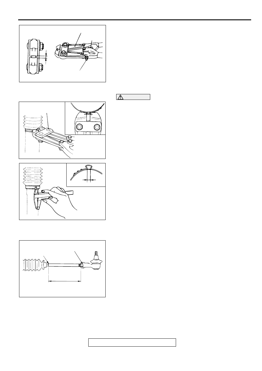
>>N<< BELLOWS BAND INSTALLATION
1. Turn the adjusting bolt of special tool MB991561 to adjust
the opening dimension (W) to the standard value.
NOTE: The dimension (W) is adjusted by approximately 0.7
mm (0.03 inch) per one turn.
NOTE: Do not turn the adjusting bolt more than one turn.
Standard value (W): 1.9 mm (0.07 inch)
<When more than 1.9 mm (0.07 inch)>: Screw in the
adjusting bolt.
<When less than 1.9 mm (0.07 inch)>: Loosen the
adjusting bolt.
CAUTION
•
Hold the rack housing, and use special tool MB991561
to crimp the bellows band securely.
•
Crimp the bellows band until special tool MB991561
touches the stopper.
2. Use special tool MB991561 to crimp the bellows band.
3. Check that crimped width (A) is within the standard value.
Standard value (A): 1.4
−
1.8 mm (0.06
−
0.07 inch)
<When more than 1.8 mm (0.07 inch)>: Readjust the
dimension (W) of step (1) to the value calculated by
the following equation, and repeat step (2).
W = 5.5 mm (0.22 inch)
−
A [Example: if (A) is 1.9 mm
(0.07 inch), (W) is 3.6 mm (0.14 inch).]
<When less than 1.4 mm (0.06 inch)>: Remove the
bellows band, readjust the dimension (W) of step (1) to
the value calculated by the following equation, and
use a new bellows band to repeat steps (2) to (3).
W = 5.5 mm (0.22 inch)
−
A [Example: if (A) is 1.3 mm
(0.05 inch), (W) is 4.2 mm (0.17 inch).]
>>O<< TIE ROD END/TIE ROD END JAM NUT
INSTALLATION
Screw in the tie rod end to achieve the right and left length as
illustrated. Lock with the jam nut.
ACX01164 AB
W
MB991561
ADJUSTING BOLT
STOPPER
ACX01165 AB
MB991561
ACX01166 AB
A
AC001011AC
JAM NUT
EDGE OF BELLOWS
ASSEMBLY GROOVE
2.4L ENGINE: 192 mm (7.6 in)
3.0L ENGINE <ECLIPSE>: 200 mm (7.9 in)
3.0L ENGINE <ECLIPSE SPYDER>: 197 mm (7.8 in)
POWER STEERING GEAR BOX ASSEMBLY
TSB Revision
POWER STEERING
37A-36
INSPECTION
M1372004400051
RACK
•
Check the rack tooth surfaces for damage or wear.
•
Check the oil seal contact surfaces for uneven wear.
•
Check the rack for bends.
PINION AND VALVE ASSEMBLY
•
Check the pinion gear tooth surfaces for damage or wear.
•
Check for worn or defective seal ring.
BEARING
•
Check for roughness or abnormal noise during bearing
operation.
•
Check the bearing for play.
•
Check the needle roller bearings for roller slip-off.
OTHERS
•
Check the cylinder inner surface of the rack housing for
damage.
•
Check the boots for damage, cracking or deterioration.
•
Check the rack support for uneven wear or dents.
•
Check the rack bushing for uneven wear or damage.
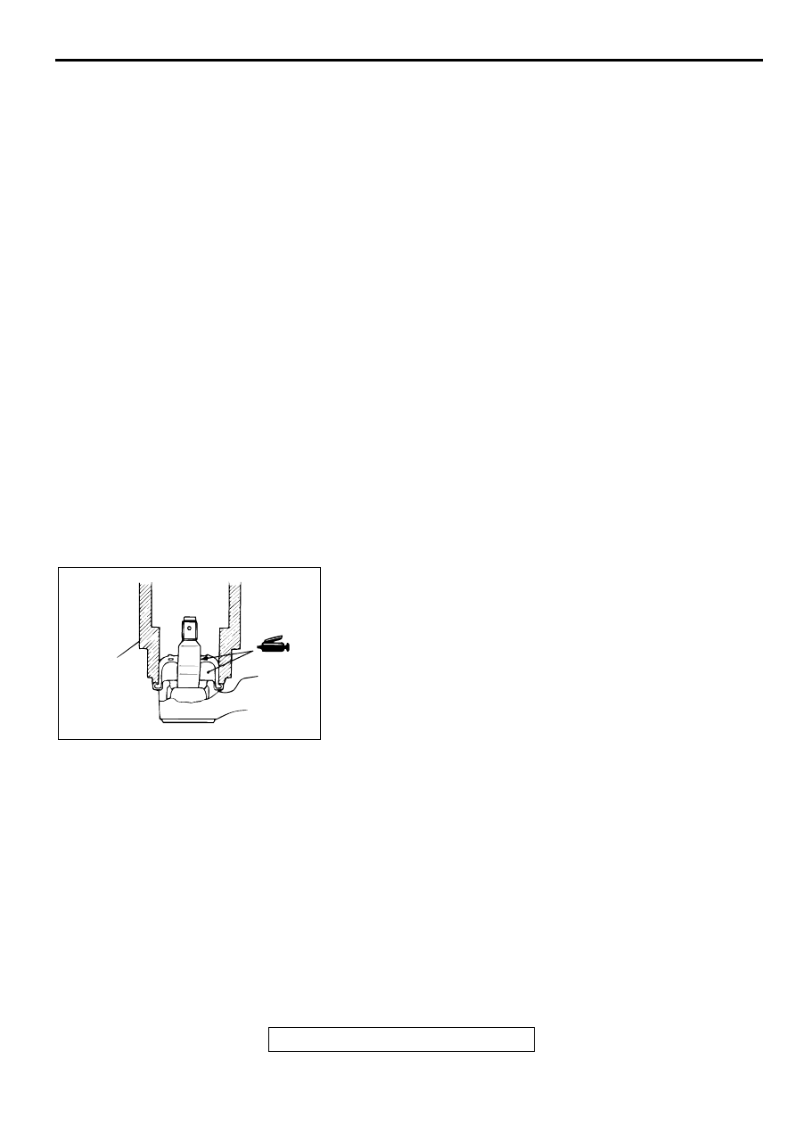
TIE ROD END BALL JOINT DUST COVER
REPLACEMENT
M1372008200093
If the dust cover is damaged accidentally during service work,
replace the dust cover as follows:
1. Apply grease to the lip and inside of the dust cover.
2. Drive in the dust cover with special tool MB990776 until it is
fully seated.
3. Check the dust cover for cracks or damage by pushing it
with your finger.
AC001012AB
MB990776
POWER STEERING OIL PUMP ASSEMBLY
TSB Revision
POWER STEERING
37A-37
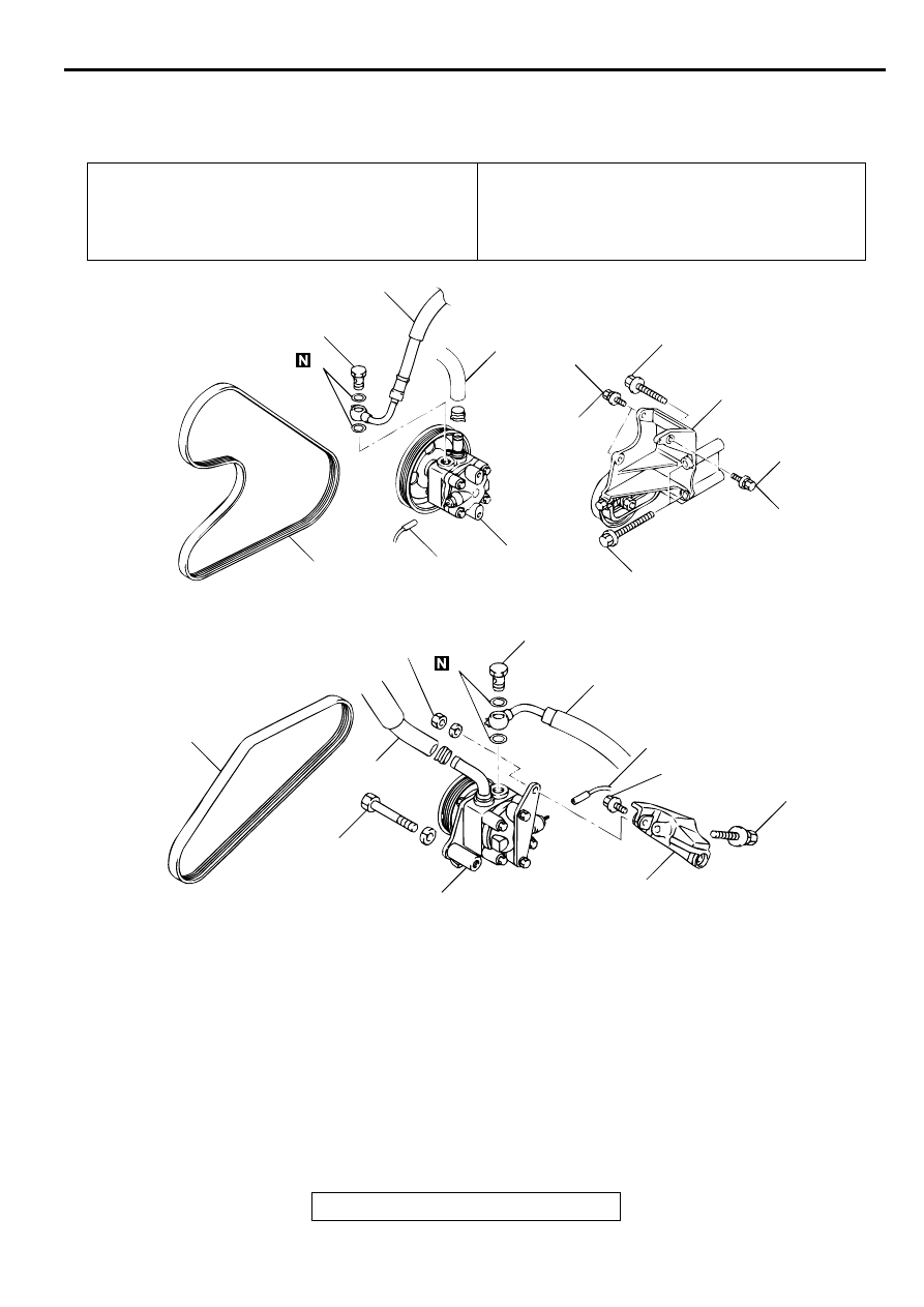
PO W ER STEER IN G O IL PU M P A SSEM BLY
REMOVAL AND INSTALLATION
M1372005200072
INSPECTION
M1372005300057
Check the drive belt for cracks.
Check the driveshaft assembly for uneven rotation.
Pre-removal Operation
•
Power Steering Fluid Draining (Refer to
Post-installation Operation
•
Power Steering Fluid Level Check (Refer to
.)
•
Drive Belt Tension Check (Refer to
.)
•
Power Steering Fluid Line Bleeding (Refer to
•
Oil Pump Pressure Test (Refer to
.)
AC001013
1
10
9
8
7
6
5
4
3
2
57 ± 7 N·m
42 ± 5 ft-lb
1
9
5
4
3
2
57 ± 7 N·m
42 ± 5 ft-lb
29 ± 3 N·m
21 ± 3 ft-lb
29 ± 3 N·m
21 ± 3 ft-lb
49 ± 10 N·m
36 ± 7 ft-lb
42 ± 7 N·m
31 ± 5 ft-lb
42 ± 7 N·m
31 ± 5 ft-lb
23 ± 4 N·m
17 ± 3 ft-lb
44 ± 10 N·m
33 ± 7 ft-lb
<2.4L ENGINE>
<3.0L ENGINE>
AB
49 ± 10 N·m
36 ± 7 ft-lb
REMOVAL STEPS
1.
DRIVE BELT
2.
PRESSURE SWITCH CONNECTOR
3.
SUCTION HOSE
4.
PRESSURE HOSE
5.
GASKET
6.
BOLT
7.
BOLT
8.
POWER STEERING PUMP
BRACKET
9.
OIL PUMP
10.
OIL PUMP BRACKET
REMOVAL STEPS (Continued)
POWER STEERING OIL PUMP ASSEMBLY
TSB Revision
POWER STEERING
37A-38
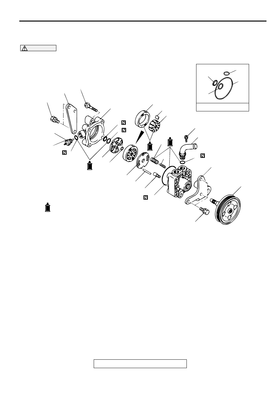
DISASSEMBLY AND ASSEMBLY
M1372005400087
CAUTION
Do not disassemble the pressure switch assembly and valve subassembly.
AC001014
OIL PUMP SEAL KIT
1
13
12
11
10
8
7
6
5
4
3
2
14
15
18
17
16
19
20
21
6
5
16
21
27 ± 2 N·m
21 ± 1 ft-lb
16 ± 2 N·m
12 ± 1 ft-lb
20 ± 3 N·m
15 ± 2 ft-lb
3.7 ± 0.3 N·m
33 ± 2 in-lb
16 ± 2 N·m
12 ± 1 ft-lb
AD
9
: MITSUBISHI POWER STEERING FLUID
DISASSEMBLY STEPS
1.
PRESSURE SWITCH ASSEMBLY
2.
O-RING
3.
REAR BRACKET <3.0L ENGINE>
4.
REAR COVER
5.
BACKUP RING
>>A<<
6.
O-RING
7.
SIDE PLATE (REAR)
8.
SNAP RING
9.
DRIVESHAFT ASSEMBLY
10.
FRONT BRACKET <3.0L ENGINE>
>>D<<
11.
VANE
>>C<<
12.
CAM RING
>>B<<
13.
ROTOR
14.
SIDE PLATE (FRONT)
15.
LOCK PIN
16.
O-RING
17.
VALVE SUBASSEMBLY
18.
SPOOL ASSEMBLY
19.
SPRING
20.
SUCTION PIPE
>>A<<
21.
O-RING
DISASSEMBLY STEPS (Continued)
Нет комментариевНе стесняйтесь поделиться с нами вашим ценным мнением.
Текст