Mitsubishi Eclipse / Eclipse Spyder (2000-2002). Service and repair manual — part 335
MULTIPORT FUEL INJECTION (MFI) DIAGNOSIS
TSB Revision
MULTIPORT FUEL INJECTION (MFI) <3.0L ENGINE>
13B-539
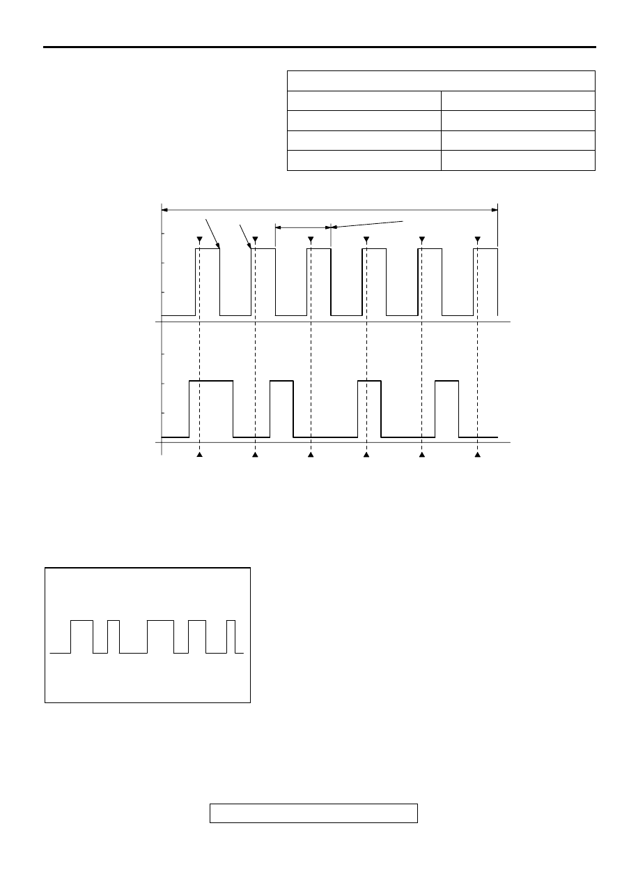
Standard Wave Pattern
Wave Pattern Observation Points
1. Check that cycle time T becomes shorter when the engine
speed increased.
Examples of Abnormal Wave Patterns
Example 1
•
Cause of problem
Sensor interface malfunction.
•
Wave pattern characteristics
Rectangular wave pattern is output even when the engine is
not started.
Observation conditions
Function
Special pattern
Pattern height
Low
Pattern selector
Display
Engine r/min
Idle speed
AKX01600
2 ENGINE REVOLUTIONS (1 CAMSHAFT REVOLUTION)
75
BTDC
5
BTDC
T
CYCLE TIME CHANGES
WITH ENGINE SPEED
CHANGES
CRANKSHAFT
POSITION
SENSOR OUTPUT
WAVE PATTERN
CAMSHAFT
POSITION
SENSOR OUTPUT
WAVE PATTERN
TDC: TOP DEAD CENTER
NO.1 TDC
NO.2 TDC
NO.3 TDC
NO.4 TDC
NO.5 TDC
NO.6 TDC
TIME
Standard wave pattern
AB
AKX01597
MULTIPORT FUEL INJECTION (MFI) DIAGNOSIS
TSB Revision
MULTIPORT FUEL INJECTION (MFI) <3.0L ENGINE>
13B-540
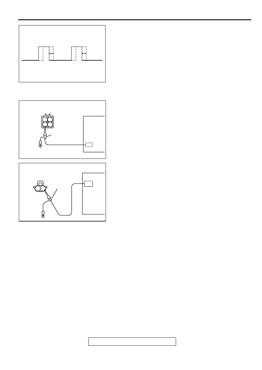
Example 2
•
Cause of problem
Loose timing belt.
Abnormality in sensor disc.
•
Wave pattern characteristics
Wave pattern is displaced to the left or right.
INJECTOR
Required Special Tools:
MB991348: Test Harness
MD998464: Test Harness
Measurement Method
<Measure at the right bank (number 1, 3, 5 cylinders)>
1. Disconnect the injector intermediate connector, and connect
the test harness special tool (MD998464) in between.
2. Connect the oscilloscope probe to each injector
intermediate connector terminal to analyze each cylinder:
•
Terminal 2 (black clip of special tool) for the number 1
cylinder
•
Terminal 3 (blue clip) for the number 3 cylinder
•
Terminal 4 (white clip) for the number 5 cylinder
<Measure at the right bank (number 2, 4, 6 cylinders)>
1. Disconnect the injector connector, and connect the test
harness special tool (MB991348) in between. (All terminals
should be connected.)
2. Connect the oscilloscope probe to injector connector
terminal 2.
Alternate method (Test harness not available)
1. Connect the oscilloscope probe to ECM <M/T> or PCM
<A/T> terminal 1. (When checking the number 1 cylinder.)
2. Connect the oscilloscope probe to ECM <M/T> or PCM
<A/T> terminal 9. (When checking the number 2 cylinder.)
3. Connect the oscilloscope probe to ECM <M/T> or PCM
<A/T> terminal 24. (When checking the number 3 cylinder.)
4. Connect the oscilloscope probe to ECM <M/T> or PCM
<A/T> terminal 2. (When checking the number 4 cylinder.)
5. Connect the oscilloscope probe to ECM <M/T> or PCM
<A/T> terminal 10. (When checking the number 5 cylinder.)
6. Connect the oscilloscope probe to ECM <M/T> or PCM
<A/T> terminal 25. (When checking the number 6 cylinder.)
AKX01602
AK000063
1 2
3 4
OSCILLOSCOPE
INJECTOR INTERMEDIATE
CONNECTOR
OSCILLO
SCOPE
PROBE
AB
AK000064
OSCILLOSCOPE
OSCILLO
SCOPE
PLOBE
1 2
AB
MULTIPORT FUEL INJECTION (MFI) DIAGNOSIS
TSB Revision
MULTIPORT FUEL INJECTION (MFI) <3.0L ENGINE>
13B-541
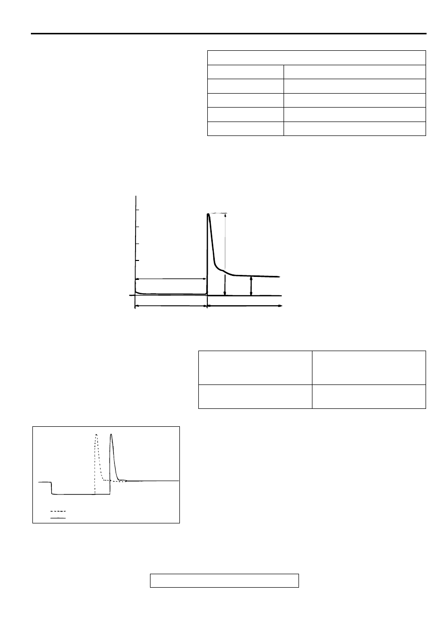
Standard Wave Pattern
Wave Pattern Observation Points
Point A: Height of injector coil induced voltage.
Point B: Injector drive time
1. The injector drive time should be synchronized with the
scan tool tester display.
2. When the engine is suddenly revved, the drive time will be
greatly extended at first, but the drive time will soon return
to original length.
Observation conditions
Function
Special pattern
Pattern height
Variable
Variable knob
Adjust while viewing the wave pattern
Pattern selector
Display
Engine r/min
Idle speed
CONTRAST WITH
STANDARD WAVE
PATTERN
PROBABLE CAUSE
Injector coil induced voltage is
low or doesn't appear at all
Short in the injector solenoid
AKX01604
(V)
50
0
DRIVE SIGNAL:"ON"
POINT B:
INJECTOR DRIVE
TIME
POINT A
DRIVE SIGNAL:"OFF"
POWER VOLTAGE
INJECTION COIL INDUCED
VOLTAGE (APPROXIMATELY 50-60 V)
AB
Standard wave pattern
AKX01605
WHEN IDLING
WHEN RACING
AB
MULTIPORT FUEL INJECTION (MFI) DIAGNOSIS
TSB Revision
MULTIPORT FUEL INJECTION (MFI) <3.0L ENGINE>
13B-542
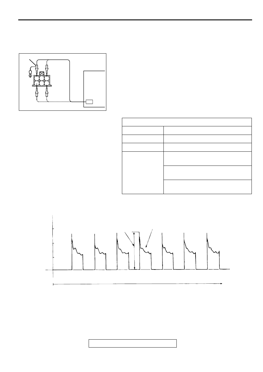
IDLE AIR CONTROL MOTOR (STEPPER MOTOR)
Required Special Tool:
MB991709: Test Harness
Measurement Method
1. Disconnect the idle air control motor connector, and connect
the test harness special tool (MB991709) in between. (All
terminals should be connected.)
2. Connect the oscilloscope probe to the idle air control motor
connector terminal 1, terminal 3, terminal 4 and terminal 6,
respectively.
Alternate method (Test harness not available)
1. Connect the oscilloscope probe to ECM <M/T> or PCM <A/
T> terminals 14, 15, 28 and 29.
Standard Wave Pattern
Wave Pattern Observation Points
1. Check that the standard wave pattern appears when the
idle air control motor is operating.
Point A:
Presence or absence of induced electromotive force from the
motor turning. (Refer to abnormal wave pattern.)
Observation conditions
Function
Special pattern
Pattern height
High
Pattern selector
Display
Engine condition
Turn the ignition switch from "OFF" to
"ON" (without starting the engine).
While the engine is idling, turn the A/C
switch to "ON."
Immediately after starting the warm the
engine (approximately one minute).
AKX01606
6
3
1 2
4 5
OSCILLOSCOPE
OSCILLOSCOPE PLOBE
AKX01606AB
AKX01607 AB
(V)
30
20
10
0
IAC
MOTOR
CONTROL
SIGNAL
WAVE
PATTERN
THE WAVE PATTERN
APPEARS FOR AN
INSTANT, BUT SOON
DISAPPEARS.
POINT B COIL RE-
VERSE ELECTRO-
MOTIVE FORCE
(APPROXIMATELY
3 x10 V)
POINT AN INDUCED
ELECTROMOTIVE
FORCE FROM THE
MOTOR TURNING
TIME
Standard wave pattern
Нет комментариевНе стесняйтесь поделиться с нами вашим ценным мнением.
Текст