Mitsubishi Eclipse / Eclipse Spyder (2000-2002). Service and repair manual — part 17
00E-1
GROUP 00E
CONTENTS
HARNESS CONNECTOR
INSPECTION . . . . . . . . . . . . . . . . . . .
HOW TO DIAGNOSE. . . . . . . . . . . . .
HOW TO DIAGNOSE . . . . . . . . . . . . . . . . .
TROUBLESHOOTING STEPS . . . . . . . . . .
INFORMATION FOR DIAGNOSIS . . . . . . .
INSPECTION . . . . . . . . . . . . . . . . . . . . . . .
INSPECTION INSTRUMENTS . . . . . . . . . .
CHECKING SWITCHES . . . . . . . . . . . . . . .
CHECKING RELAYS . . . . . . . . . . . . . . . . .
CHECKING FUSES. . . . . . . . . . . . . . . . . . .
CABLES AND WIRES CHECK . . . . . . . . . .
BATTERY HANDLING . . . . . . . . . . . . . . . .
GENERAL ELECTRICAL SYSTEM
CHECK . . . . . . . . . . . . . . . . . . . . . . . . . . . .
HARNESS CONNECTOR INSPECTION
TSB Revision
GENERAL <ELECTRICAL>
00E-2
.
HA RN ESS C O N N EC TO R IN SPEC TIO N
M1001003900030
CONNECTOR CONTINUITY AND VOLTAGE TEST
Required Special Tools:
•
MB991219: Test Harness Set
•
MD998459: Test Harness
Follow the steps below to avoid causing poor connector contact
and/or reduced waterproof performance of connectors when
checking continuity and/or voltage at connectors of waterproof
connectors.
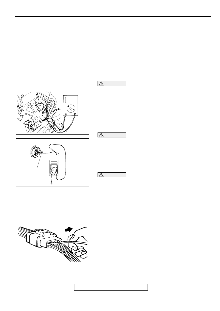
CAUTION
Never backprobing a waterproof connector. Backprobing a
connector may cause the terminals to corrode,
deteriorating circuit performance.
1. If checking is performed with the circuit in the state of
continuity, to use special tool MD998459.
CAUTION
Forcing the probe into the terminal may open the terminal,
causing intermittent or poor contact and creating an open
circuit.
2. If the connector is disconnected for checking and the facing
part is the female pin side, the harness for checking the
contact pressure of connector pins (MB991219) should be
used.
CAUTION
Do not simultaneously contact more than one terminal
with the probe. Contacting two or more terminals at the
same time may damage a circuit, possibly to the point of
starting an electrical fire.
3. If the facing part is the male pin side, contact the test probe
directly at the pins.
IMPROPER TERMINAL ENGAGEMENT CHECK
Terminals inside a connector may not engage properly even if
the connectors engage. Make sure that each terminal does not
come out of the connector when gently pulling each harness
wire. If it does, repair or replace the connector.
AC000014 AB
MD998459
AC000015 AB
MB991219
AC000016
HARNESS CONNECTOR INSPECTION
TSB Revision
GENERAL <ELECTRICAL>
00E-3
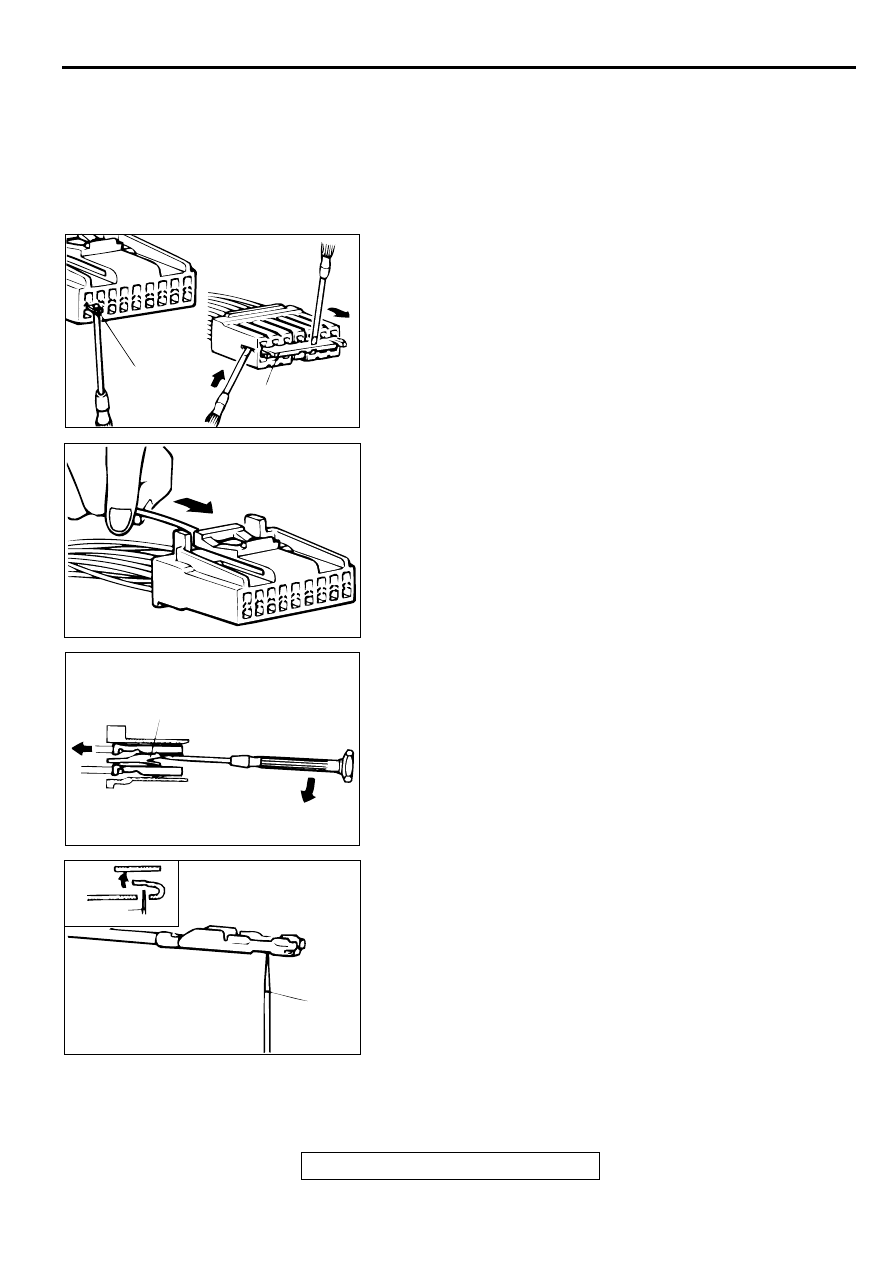
CONNECTOR TERMINAL ENGAGEMENT AND
DISENGAGEMENT
Loosely engaged terminals can be repaired by removing the
female terminal from the connector housing and raising its
lance to establish better engagement. Removal of the
connector terminal used for MFI and INVECS-II A/T control
circuit can be done in the following manner.
COMPUTER CONNECTOR
1. Insert a screwdriver [1.4 mm (0.06 inch) width] as shown in
the figure, disengage front holder, and remove it.
2. Push the harness wire of the terminal to be repaired deep
into the connector from the harness side and hold it there.
3. Insert the tip of the screwdriver [1.4 mm (0.06 inch) width]
into the connector as shown in the figure, raise the housing
lance slightly with the tip, and pull out the terminal.
4. Insert a needle through the hole provided on the terminal
and raise the contact point. Lightly squeeze the outer edge
so the flats are parallel with the bottom.
ACX00904AB
FRONT
HOLDER
FRONT HOLDER
ACX00905
ACX00906 AB
HOUSING LANCE
ACX00907 AB
NEEDLE
NEEDLE
HARNESS CONNECTOR INSPECTION
TSB Revision
GENERAL <ELECTRICAL>
00E-4
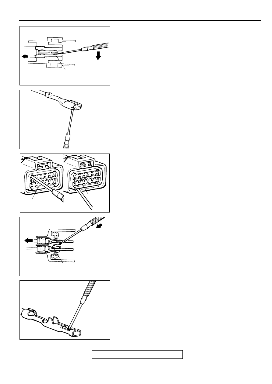
ROUND WATERPROOF CONNECTOR
1. Remove the waterproof cap by using a screwdriver.
2. Insert the tip of the screwdriver [1.4 mm (0.06 inch) or 2.0
mm (0.08 inch) width] into the connector as shown in the
figure, raise the housing lance slightly with the tip, and pull
out the terminal.
3. Insert a screwdriver through the hole provided on the
terminal and raise the contact point. Lightly squeeze the
outer edge so the flats are parallel with the bottom.
RECTANGULAR WATERPROOF CONNECTOR
1. Disengage the front holder with a screwdriver and remove it.
2. Insert the tip of a screwdriver [0.8 mm (0.03 inch) width] into
the connector as shown in the figure, push it lightly to raise
the housing lance, and pull out the terminal.
3. Press the contact point of the male terminal down by holding
a screwdriver [1.4 mm (0.06 inch) width] as shown in the
figure. Lightly squeeze the outer edge so the flats are
parallel with the bottom.
ACX00908 AB
HOUSING LANCE
ACX00909
ACX00910AB
FRONT HOLDER
FRONT
HOLDER
ACX00911AB
HOUSING LANCE
ACX00912
Нет комментариевНе стесняйтесь поделиться с нами вашим ценным мнением.
Текст