Mitsubishi Eclipse / Eclipse Spyder (2000-2002). Service and repair manual — part 600

TRACTION CONTROL SYSTEM (TCL) DIAGNOSIS
TSB Revision
TRACTION CONTROL SYSTEM (TCL)
35C-35
INSPECTION PROCEDURE 6: The TCL System does not Operate.
TECHNICAL DESCRIPTION (COMMENT)
The cause depends on driving and road surface
conditions, so diagnosis may be difficult. However, if
no diagnostic trouble code is displayed, carry out the
following inspection.
TROUBLESHOOTING HINTS (The most likely
cause for this case:)
Malfunction of the hydraulic unit
DIAGNOSIS
Check the hydraulic unit (Refer to
.). If the hydraulic
unit (integrated with ABS-ECU) is malfunctioning, replace it.
Then check that the malfunction symptom is eliminated.
DATA LIST REFERENCE TABLE
M1354003000043
The following items can be read by the scan tool
from the ABS-ECU input data.
ACTUATOR TEST REFERENCE TABLE
M1354003100040
The scan tool activates the following actuators for
testing.
NOTE: If the ABS-ECU is inoperative, actuator
testing cannot be carried out.
NOTE: Actuator testing is only possible when the
vehicle is stationary. If the vehicle speed during
actuator testing exceeds 10 km/h (6 mph), forced
actuation will be canceled.
MUT-II
SCAN
TOOL
DISPLAY
ITEM
NO.
CHECK ITEM
CHECKING REQUIREMENTS NORMAL VALUE
BATT.
VOLTAGE
16
ABS-ECU power supply voltage Ignition switch power supply
voltage and valve monitor
voltage
9
−
16 V
FL SNSR
12
Front-left wheel speed sensor
Drive the vehicle
Vehicle speeds
displayed on the
speedometer and
scan tool are
identical.
FR SNSR
11
Front-right wheel speed sensor
RL SNSR
14
Rear-left wheel speed sensor
RR SNSR
13
Rear-right wheel speed sensor
STOPLIGH
T SW
36
Stoplight switch
Depress the brake pedal.
ON
Release the brake pedal.
OFF
TRACTION CONTROL SYSTEM (TCL) DIAGNOSIS
TSB Revision
TRACTION CONTROL SYSTEM (TCL)
35C-36
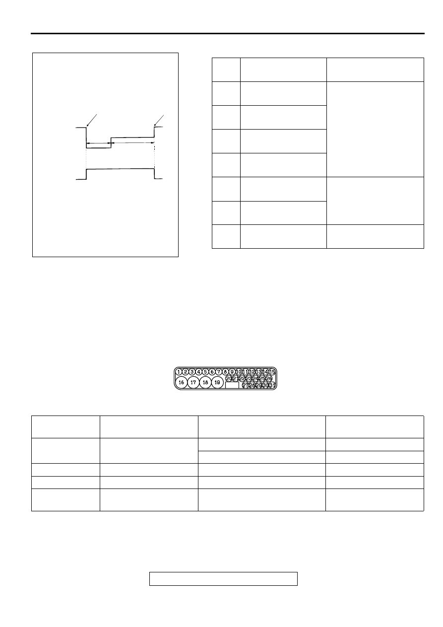
ACTUATOR TEST SPECIFICATIONS
CHECK AT ABS-ECU
M1354003200047
TERMINAL VOLTAGE CHECK CHART
1. Measure the voltages between terminals (16),
(19) and (30) (ground terminals) and each
respective terminal.
2. The terminal layouts are shown in the illustration
below.
NOTE: Do not measure terminal voltage for
approximately three seconds after the ignition
switch is turned to "ON." The ABS-ECU performs
the initial check during that period.
NO.
ITEM
PARTS TO BE
ACTIVATED
01
ABS solenoid valve for
front-left wheel
Solenoid valves and
pump motor in the
hydraulic unit (simple
inspection mode)
02
ABS solenoid valve for
front-right wheel
03
ABS solenoid valve for
rear-left wheel
04
ABS solenoid valve for
rear-right wheel
06
TCL solenoid valve for
front-right wheel
TCL valves and pump
motor in the hydraulic unit
(simple inspection mode)
07
TCL solenoid valve for
front-left wheel
12
Pump motor
Activate the pump motor
for two seconds.
AC000971AB
ACTIVATION PATTERN (NO.06,07)
A
B
C
TCL
SOLENOID
VALVE
END OF
FORCED
ACTION
START OF
FORCED
ACTION
1 s
2 s
PUMP
MOTOR
ON
OFF
NOTE
A:
B:
C:
HYDRAULIC PRESSURE DECREASES
HYDRAULIC PRESSURE HOLDS
HYDRAULIC PRESSURE INCREASES
AC002089 AB
CONNECTOR
TERMINAL NO.
SIGNAL
CHECKING REQUIREMENT
NORMAL CONDITION
14
Input from stoplight
switch
Stoplight switch: ON
System voltage
Stoplight switch: OFF
Approximately 0 V
15
ABS-ECU power supply
Ignition switch: "ON"
System voltage
17
Motor power supply
Always
System voltage
18
Solenoid valve power
supply
Always
System voltage
TRACTION CONTROL SYSTEM (TCL) DIAGNOSIS
TSB Revision
TRACTION CONTROL SYSTEM (TCL)
35C-37
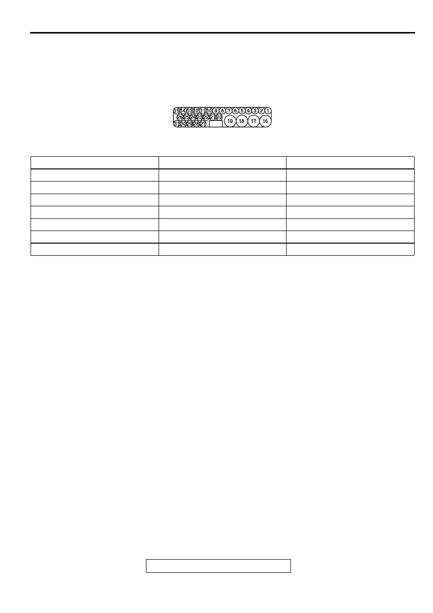
RESISTANCE AND CONTINUITY BETWEEN
HARNESS-SIDE CONNECTOR TERMINALS
1. Turn the ignition switch to the "LOCK" (OFF)
position and disconnect the ABS-ECU connectors
before checking resistance and continuity.
2. Check between the terminals indicated in the
table below.
3. The terminal layouts are shown in the illustration
below.
AC002090 AB
CONNECTOR TERMINAL NO.
SIGNAL
NORMAL CONDITION
6
−
7
Front-left wheel speed sensor
1.28
−
1.92 k
Ω
1
−
3
Rear-right wheel speed sensor
1.28
−
1.92 k
Ω
4
−
5
Front-right wheel speed sensor
1.28
−
1.92 k
Ω
8
−
9Rear-left wheel speed sensor
1.28
−
1.92 k
Ω
16
−
body ground
Solenoid valve ground
Less than 2
Ω
19
−
body ground
Motor ground
Less than 2
Ω
30
−
body ground
TCL solenoid valve ground
Less than 2
Ω
SPECIAL TOOLS
TSB Revision
TRACTION CONTROL SYSTEM (TCL)
35C-38
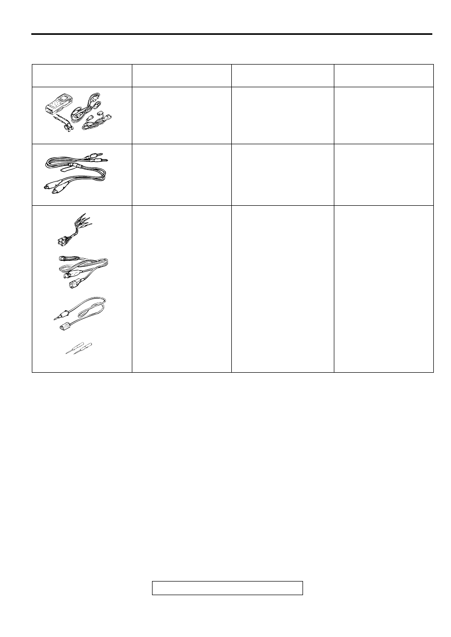
SPECIA L TO O LS
M1354000200037
TOOL
TOOL NUMBER AND
NAME
SUPERSESSION
APPLICATION
MB991502
Scan tool (MUT-II)
MB991496-OD
For checking of TCL
(Diagnostic trouble code
display when using the
scan tool)
MB991529
Diagnostic trouble code
check harness
Tool not necessary if scan
tool (MUT-II) is available.
For checking of TCL
(Diagnostic trouble code
display when using the
TCL warning light)
MB991223
Harness set
A:MB991219
Inspection harness
B:MB991220
LED harness
C:MB991221
LED harness adaptor
D:MB991222
Probe
MB991223
MB991709-01
Making voltage and
resistance measurement
during troubleshooting
A: Connector pin contact
B: Power circuit
inspection
C: Power circuit
inspection
D: Commercial tester
connection
B991502
MB991529
MB991223
A
AB
B
C
D
Нет комментариевНе стесняйтесь поделиться с нами вашим ценным мнением.
Текст