Mitsubishi Eclipse / Eclipse Spyder (2000-2002). Service and repair manual — part 589
ON-VEHICLE SERVICE
TSB Revision
ANTI-LOCK BRAKING SYSTEM (ABS)
35B-47
HYDRAULIC UNIT CHECK
M1352001700084
Required Special Tool:
MB991502: Scan Tool (MUT-II)
CAUTION
•
The roller of the braking force tester and the tire should
be dry during testing.
•
When testing the front brakes, apply the parking brake.
When testing the rear brakes, stop the front wheels
with chocks.
1. Jack up the vehicle. Then support the vehicle with rigid
racks at the specified jack-up points or place the front or rear
wheels on the rollers of the braking force tester.
2. Release the parking brake, and feel the drag force (drag
torque) on each road wheel. When using the braking force
tester, take a reading of the brake drag force.
CAUTION
To prevent damage to scan tool MB991502, always turn the
ignition switch to the "LOOK" (OFF) position before
connecting or disconnecting scan tool MB991502.
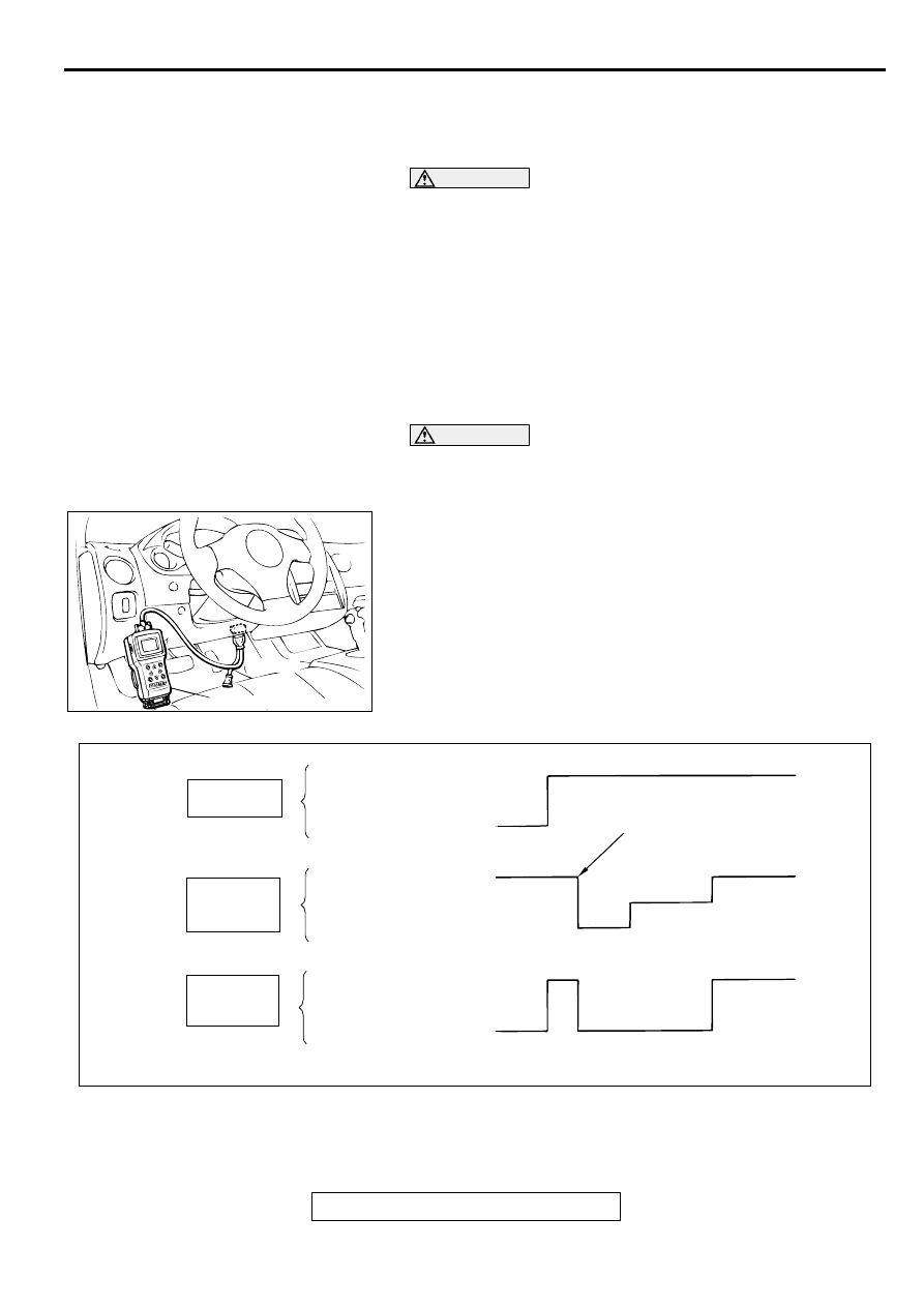
3. Turn the ignition switch to the "LOCK" (OFF) position and
set scan tool MB991502 as shown in the illustration.
4. After checking that the shift lever <M/T> or the selector lever
<A/T> is in neutral, start the engine.
5. Use scan tool MB991502 to force-drive the actuator.
NOTE: The ABS system will switch to the scan tool mode
and the ABS warning light will illuminate.
NOTE: When the ABS has been interrupted by the fail-safe
function, scan tool MB991502 actuator testing cannot be
used.
AC001252AF
16 PIN
MB991502
AC000954AB
SCAN TOOL ACTUATOR TEST
(ITEM NO.01, 02, 03, 04) START
1 s
2 s
3 s
DEPRESSED
RELEASED
PRESSURE INCREASE
PRESSURE DECREASE
PRESSURE HOLD
LOCK
DRAG FORCE
WHEN THE
PEDAL IS FREE
PEDAL
OPERATION
SOLENOID
VALVE
POSITION
CHECKING
THE BRAKE
FORCE
ON-VEHICLE SERVICE
TSB Revision
ANTI-LOCK BRAKING SYSTEM (ABS)
35B-48
6. Turn the wheel by hand and check the change in braking
force when the brake pedal is depressed. When using the
braking force tester, depress the brake pedal until the
braking force is at the following values, and check that the
braking force changes to the brake drag force inspected in
step 2 when the actuator is force-driven. The result should
be as shown in the diagram above.
7. If the result of inspection is abnormal, repair according to the
Diagnosis Table below.
8. After inspection, disconnect the scan tool immediately after
turning the ignition switch to the "LOCK" (OFF) position.
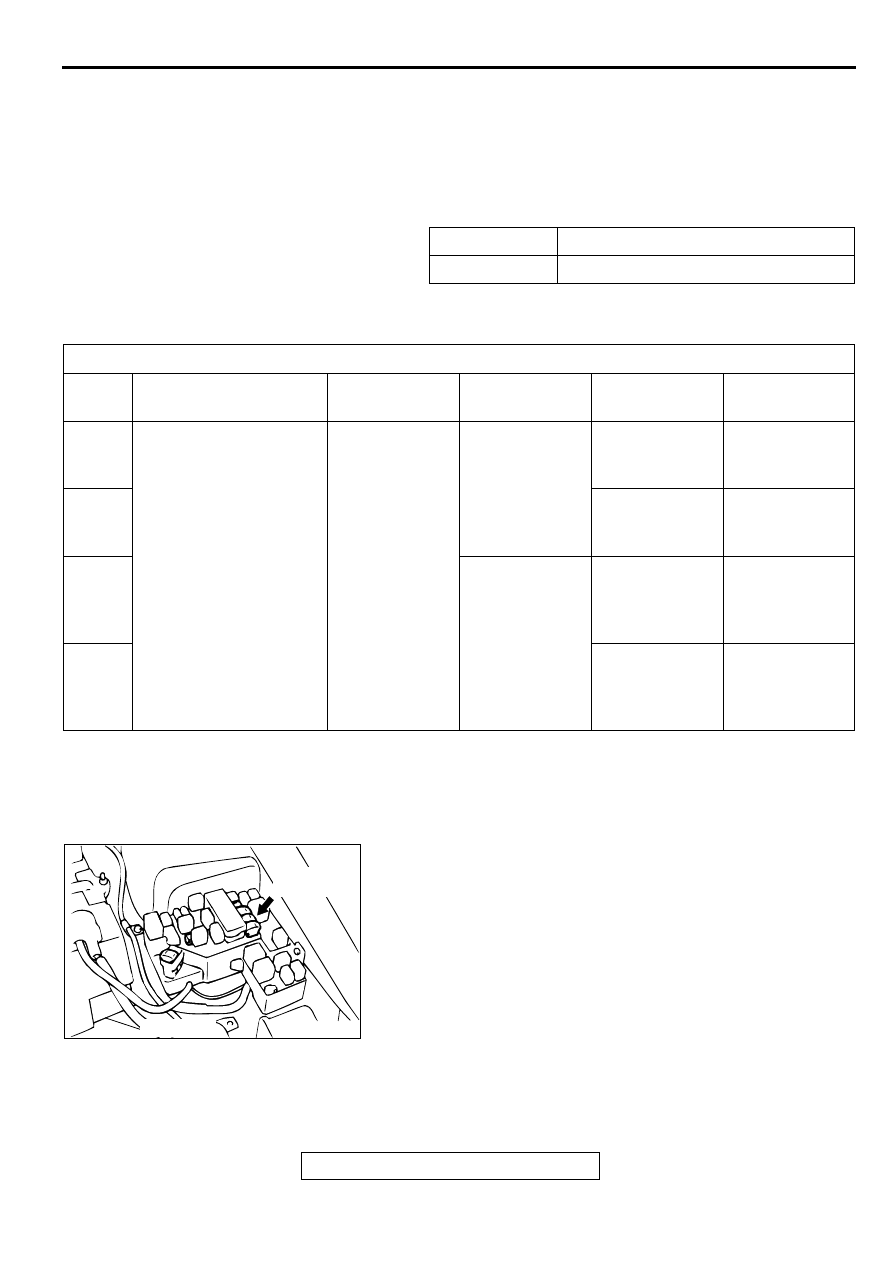
DISCHARGED BATTERY
M1352003500097
The ABS system consumes a large amount of battery current
for its self-check function. If the battery is completely
discharged and booster cables are used to start the engine, the
engine must be allowed to idle for a few minutes to recharge. If
the battery does not recharge, the engine may misfire or stall.
To prevent this condition,
•
allow the engine to idle for a few minutes before driving the
vehicle, or
•
temporarily disable the ABS system by removing the fusible
link for the ABS circuit. The ABS warning light will illuminate
when the ABS fusible link is removed. After the battery is
recharged, reinstall the ABS fusible link and check that the
ABS warning light is not illuminated.
Front wheel
785
−
981 N (176
−
220 lb.)
Rear wheel
588
−
784 N (132
−
176 lb.)
DIAGNOSIS TABLE
NO.
OPERATION
NORMAL
CONDITION
ABNORMAL
CONDITION
PROBABLE
CAUSE
REMEDY
01
1. Depress brake pedal
to lock wheel.
2. Using scan tool
MB991502, select the
wheel to be checked
and force the actuator
to operate.
3. Turn the selected
wheel manually to
check the change of
brake force.
Brake force
released for
three locking.
Wheel does not
lock when brake
pedal is
depressed.
Clogged brake
line other than
hydraulic unit
Check and clean
brake line
02
Clogged
hydraulic circuit
in hydraulic unit
Replace
hydraulic unit
assembly
03
Brake force is
not released
Incorrect
hydraulic unit
brake tube
connection
Connect
correctly
04
Hydraulic unit
solenoid valve
not functioning
correctly
Replace
hydraulic unit
assembly
ACX02443
ACX02443AE
BATTERY
FUSIBLE
LINK
MASTER CYLINDER AND BRAKE BOOSTER
TSB Revision
ANTI-LOCK BRAKING SYSTEM (ABS)
35B-49
M A STER C YLIN D ER A N D BR AK E BO O STER
REMOVAL AND INSTALLATION
M1352004000062
Refer to GROUP 35A, Master Cylinder and Brake
Booster
MASTER CYLINDER
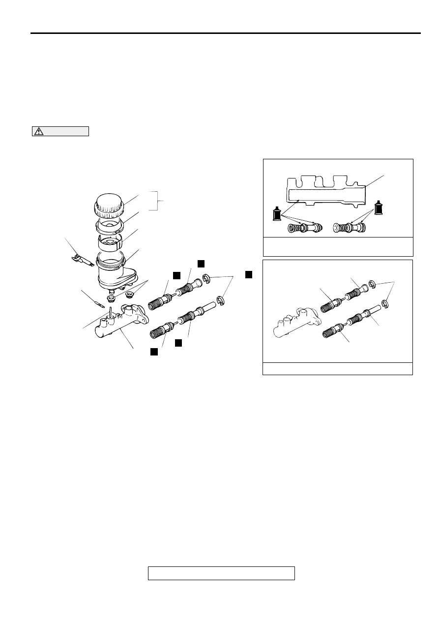
M1352004500067
DISASSEMBLY AND ASSEMBLY
CAUTION
Do not disassemble the primary and secondary piston assemblies.
AC000955
1
2
3
4
7
6
5
8
9
13
N
12
11
N
N
12
11
N
10
N
<VEHICLES WITHOUT TCL>
<VEHICLES WITHOUT TCL>
<VEHICLES WITH TCL>
<VEHICLES WITH TCL>
12
11
10
11
12
13
BRAKE FLUID:
CONFORMING TO DOT3 OR DOT4
BRAKE MASTER CYLINDER KIT
AC
DISASSEMBLY STEPS
1. RESERVOIR CAP ASSEMBLY
2. RESERVOIR CAP
3. DIAPHRAGM
4. FILTER
5. SPRING PIN
6. BRAKE FLUID LEVEL SENSOR
7. RESERVOIR
8. RESERVOIR SEAL
9. PIN
<<A>>
10. PISTON STOPPER RING
11. PRIMARY PISTON ASSEMBLY
12. SECONDARY PISTON ASSEMBLY
13. MASTER CYLINDER BODY
DISASSEMBLY STEPS (Continued)
MASTER CYLINDER AND BRAKE BOOSTER
TSB Revision
ANTI-LOCK BRAKING SYSTEM (ABS)
35B-50
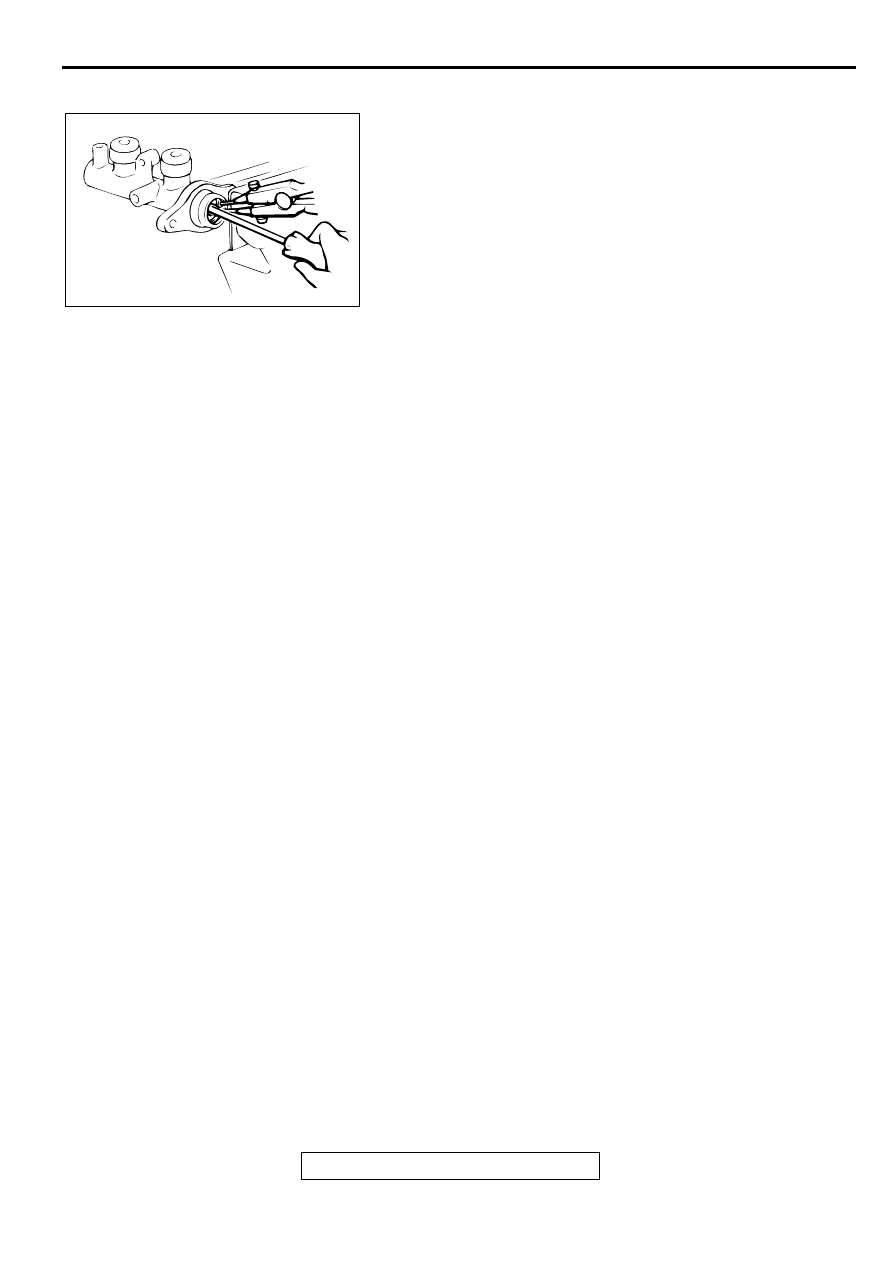
DISASSEMBLY SERVICE POINT
<<A>> PISTON STOPPER RING DISASSEMBLY
While depressing the piston, remove the piston stopper ring.
INSPECTION
M1352004600064
•
Check the inner surface of the master cylinder body for
corrosion or pitting.
•
Check the primary and secondary pistons for corrosion,
scoring, wear or damage.
•
Check the diaphragm for cracks and wear.
AC000903
Нет комментариевНе стесняйтесь поделиться с нами вашим ценным мнением.
Текст