Mitsubishi Eclipse / Eclipse Spyder (2000-2002). Service and repair manual — part 106
MULTIPORT FUEL INJECTION (MFI) DIAGNOSIS
TSB Revision
MULTIPORT FUEL INJECTION (MFI) <2.4L ENGINE>
13A-123
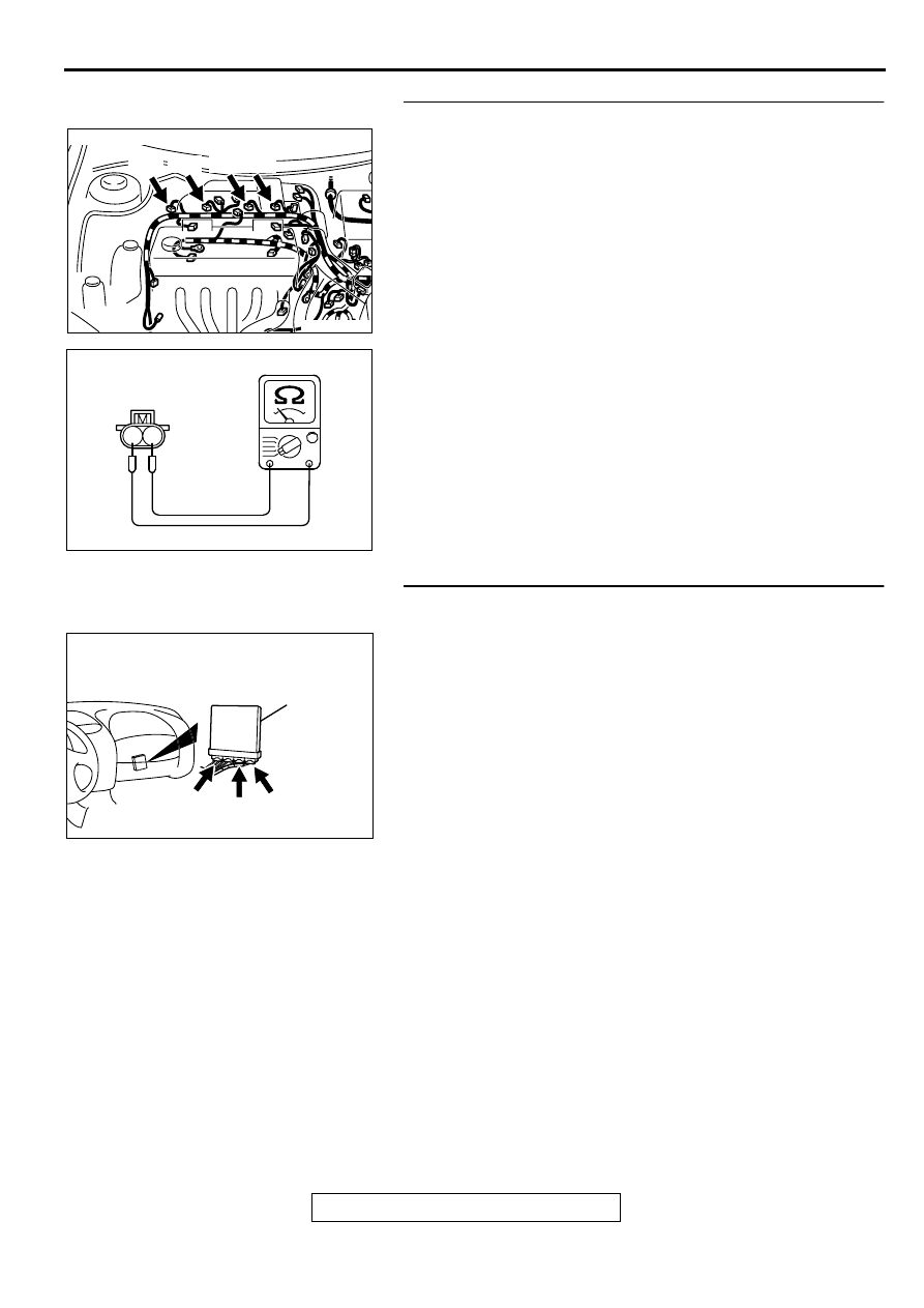
STEP 6. Check the injector.
(1) Disconnect each injector connector.
(2) Measure the resistance between injector side connector
terminal 1 and 2.
Standard value: 13
−
16 ohm [at 20
°
C (68
°
F)]
Q: Is the resistance standard value?
YES : Go to Step 7.
NO : Replace the injector. Then go to Step 11.
STEP 7. Check connector C-49, C-60 at ECM <M/T> or
connector C-50, C-57 at PCM <A/T> for damage.
Q: Is the connector in good condition?
YES : Go to Step 8.
NO : Repair or replace it. Refer to GROUP 00E, Harness
Connector Inspection (
AK000273AB
AK000273
CONNECTOR : B-01, B-02, B-05, B-06
B-01 B-02 B-05 B-06
AK000559
2
1
INJECTOR SIDE
CONNECTOR
AB
AK000280
C-49,
C-50
C-57
C-60
ECM<M/T>
OR
PCM<A/T>
CONNECTORS:C-49,C-60<M/T>,
C-50,C-57<A/T>
BF
MULTIPORT FUEL INJECTION (MFI) DIAGNOSIS
TSB Revision
MULTIPORT FUEL INJECTION (MFI) <2.4L ENGINE>
13A-124
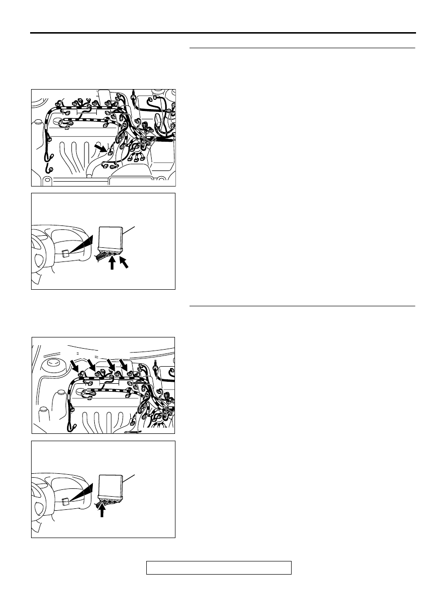
STEP 8. Check for harness damage between heated
oxygen sensor (front) connector B-17 terminal 4 and ECM
connector C-60 terminal 76 <M/T> or PCM connector C-57
terminal 71 <A/T>.
Q: Is the harness wire in good condition?
YES : Go to Step 9.
NO : Repair it. Then go to Step 11.
STEP 9. Check for harness damage between injector
connector and ECM connector <M/T> or PCM connector
<A/T>.
a. Check the harness wire between injector connector B-01
terminal 2 and ECM connector C-49 terminal 1 <M/T> or
PCM connector C-50 terminal 1 <A/T> when checking No.1
cylinder.
b. Check the harness wire between injector connector B-02
terminal 2 and ECM connector C-49 terminal 14 <M/T> or
PCM connector C-50 terminal 9 <A/T> when checking No.2
cylinder.
c. Check the harness wire between injector connector B-05
terminal 2 and ECM connector C-49 terminal 2 <M/T> or
PCM connector C-50 terminal 24 <A/T> when checking
No.3 cylinder.
d. Check the harness wire between injector connector B-06
terminal 2 and ECM connector C-49 terminal 15 <M/T> or
PCM connector C-50 terminal 2 <A/T> when checking No.4
cylinder.
Q: Is the harness wire in good condition?
YES : Go to Step 10.
NO : Repair it. Then go to Step 11.
AK000272AB
AK000272
CONNECTOR : B-17
AK000280
C-60
ECM<M/T>
OR
PCM<A/T>
CONNECTORS:C-60<M/T>,C-57<A/T>
BE
C-57
AK000273AB
AK000273
CONNECTOR : B-01, B-02, B-05, B-06
B-01 B-02 B-05 B-06
AK000280
C-49,C-50
ECM<M/T>
OR
PCM<A/T>
CONNECTORS:C-49<M/T>,C-50<A/T>
BC
MULTIPORT FUEL INJECTION (MFI) DIAGNOSIS
TSB Revision
MULTIPORT FUEL INJECTION (MFI) <2.4L ENGINE>
13A-125
STEP 10. Check the fuel pressure.
Refer to, Fuel Pressure Test (
Q: Is the fuel pressure normal?
YES : Replace the ECM or PCM. Then go to Step 11.
NO : Repair it. Then go to Step 11.
STEP 11. Test the OBD-II drive cycle.
(1) Carry out a test drive with the drive cycle pattern. Refer to,
Procedure 6
−
Other Monitor (
).
(2) Check the diagnostic trouble code (DTC).
Q: Is the DTC P0134 is output?
YES : Retry the troubleshooting.
NO : The inspection is complete.
MULTIPORT FUEL INJECTION (MFI) DIAGNOSIS
TSB Revision
MULTIPORT FUEL INJECTION (MFI) <2.4L ENGINE>
13A-126
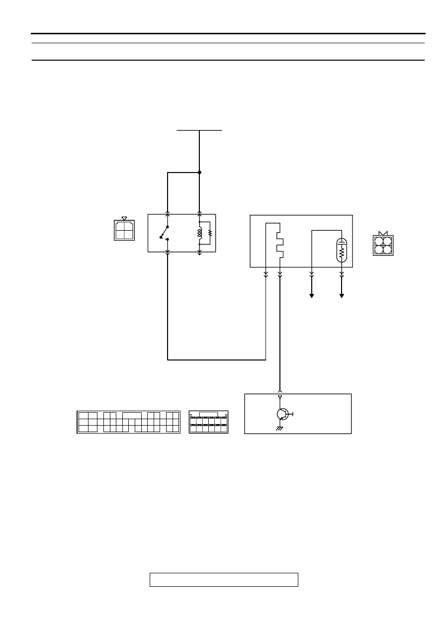
DTC P0135: O
2
Sensor Heater Circuit Malfunction (sensor 1)
AK000658
3 4
1 2
3 4
1 2
57 58
60 61
53
52
51
55
54
56
59
62
RED-
WHITE
RED-
WHITE
RED-
WHITE
RED
BR
O
WN-WHITE
BATTERY
A-21X
3
4
1
2
HEATED OXYGEN
SENSOR(FRONT)
B-17
MU802605
1
2
3
4
TO ECM
OR PCM
TO ECM
OR PCM
ENGINE CONTROL
MODULE(ECM)<M/T>
OR
POWERTRAIN CONTROL
MODULE(PCM)<A/T>
60<M/T>
3<A/T>
C-50<A/T>
(MU803784)
C-56<M/T>
(MU803770)
MFI
RELAY
2
3 4
5 6
7 8
9
11 12 13 14 15 16 17 18 19 20
30
21 22 23
24 25
26 27 28 29
3132 33
34 35
1
10
Нет комментариевНе стесняйтесь поделиться с нами вашим ценным мнением.
Текст