Mitsubishi Eclipse / Eclipse Spyder (2000-2002). Service and repair manual — part 77

MULTIPORT FUEL INJECTION (MFI) DIAGNOSIS
TSB Revision
MULTIPORT FUEL INJECTION (MFI) <2.4L ENGINE>
13A-7
NOTE: If the Service Engine Soon/Malfunction Indicator Lamp illuminates because of a malfunction of the
engine control module (ECM) <M/T> or powertrain control module (PCM) <A/T>, transmission between scan
tool MUT-II (MB991502) and the ECM <M/T> or PCM <A/T> is impossible. In this case, the diagnostic trouble
code (DTC) cannot be read.
NOTE: After the ECM <M/T> or PCM <A/T> has detected a malfunction, the Service Engine Soon/
Malfunction Indicator Lamp illuminates when the engine is next turned on and the same malfunction is re-
detected.
NOTE: After the Service Engine Soon/Malfunction Indicator Lamp illuminates, it will be switched off under the
following conditions.
.
•
When the ECM <M/T> or PCM <A/T> monitored the power train malfunction three times* it met set
condition requirements, it detected no malfunction. *: In this case, "one time" indicates from engine start to
stop.
•
For misfiring or a fuel trim malfunction, when driving conditions (engine speed, engine coolant
temperature, etc.) are similar to those when the malfunction was first recorded.
NOTE: Sensor 1 indicates the sensor mounted at a position closest to the engine, and sensor 2 indicates the
sensor mounted at the position second closest to the engine.
HOW TO READ AND ERASE DIAGNOSTIC
TROUBLE CODE
Required Special Tool:
MB991502: Scan Tool (MUT-II)
P0443
Evaporative emission control system purge control valve circuit malfunction
P0446
Evaporative emission control system vent control malfunction
P0450
Evaporative emission control system pressure sensor malfunction
P0451
Evaporative emission control system pressure sensor range/performance
P0455
Evaporative emission control system leak detected (Gross leak)
P0500
Vehicle speed sensor malfunction
P0506
Idle control system RPM lower than expected
P0507
Idle control system RPM higher than expected
P0551
Power steering pressure sensor circuit range/performance
P0705
Transmission range sensor circuit malfunction (RPNDL input)
P0710
Transmission fluid temperature sensor circuit malfunction
P0715
Input/Turbine speed sensor circuit malfunction
P0720
Output speed sensor circuit malfunction
P0725
Engine speed input circuit malfunction
P0740
Torque converter clutch system malfunction
P0750
Shift solenoid A malfunction
P0755
Shift solenoid B malfunction
P0760
Shift solenoid C malfunction
P0765
Shift solenoid D malfunction
P1400
Manifold differential pressure sensor circuit malfunction
P1751
A/T control relay malfunction
DTC NO.
ITEMS
MULTIPORT FUEL INJECTION (MFI) DIAGNOSIS
TSB Revision
MULTIPORT FUEL INJECTION (MFI) <2.4L ENGINE>
13A-8
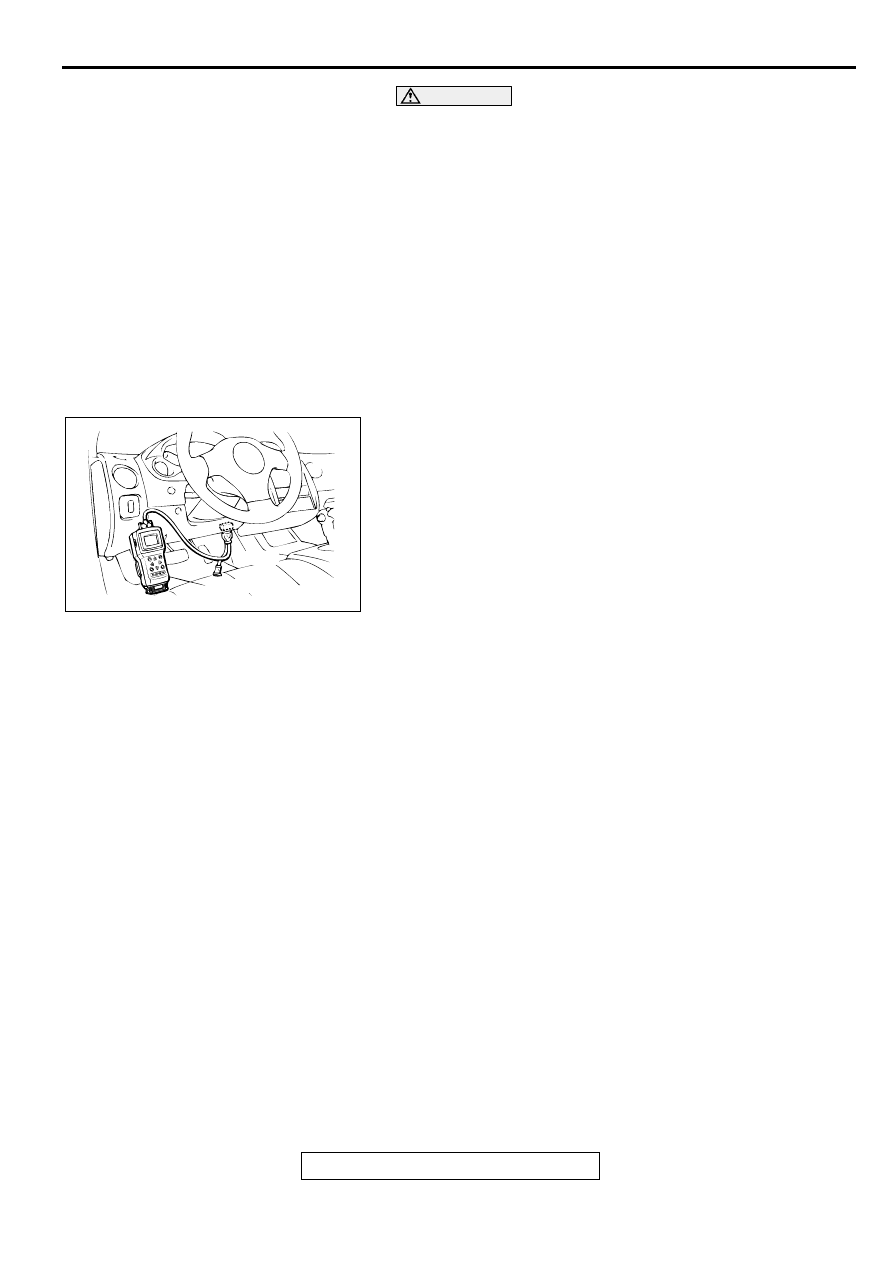
CAUTION
To prevent damage to scan tool MB991502, always turn the
ignition switch to the "LOCK" (OFF) position before
connecting or disconnecting scan tool MB991502.
NOTE: If Battery positive voltage is low, diagnostic trouble
codes may not be output. Be sure to check the battery and
charging system before continuing.
NOTE: If battery cable is disconnected or if the engine control
module (ECM) connector <M/T> or powertrain control module
(PCM) connector <A/T> is disconnected, the diagnostic trouble
codes will be erased. Do not disconnect the battery cable or
ECM <M/T> or PCM <A/T> connector until the diagnostic
trouble codes have been recorded.
NOTE: If a DTC is erased, its "freeze frame" data will be also
erased and the readiness test status will be reset. If necessary,
store the "freeze frame" data before erasing the DTC.
1. Connect scan tool MB991502 to the data link connector.
2. Turn the ignition switch to the "ON" position.
3. Read the diagnostic trouble codes for MFI.
4. Refer to the DIAGNOSTIC TROUBLE CODE CHART
(
5. Turn the ignition switch to the "LOCK" (OFF) position and
then back to "ON" again.
6. Erase the diagnostic trouble code(s) using MUT-II screen
prompts.
7. Confirm that the diagnostic trouble code output is normal.
8. Turn the ignition switch to the "LOCK" (OFF) position.
9. Disconnect scan tool MB991502 from the data link
connector.
PROVISIONAL DTCs [MUT-II OBD-II Test Mode
−
Results (Mode 5)]
The MUT-II will display the Provisional DTCs reported by
engine control module (ECM) <M/T> or powertrain control
module (PCM) <A/T> if the ECM <M/T> or PCM <A/T> detects
some malfunction for "Misfire", "Fuel System" and
"Comprehensive" monitoring during a SINGLE Driving Cycle.
The intended use of this data is to assist the technician after a
vehicle repair, and after clearing diagnostic information, by
reporting test result after a SINGLE Driving Cycle. Note that the
test results reported by this mode do not necessarily indicate a
faulty component/system. If test results indicate a failure after
ADDITIONAL (consecutive) driving, then the MIL will be
illuminated and a DTC will set.
MODE 6 REFERENCE TABLE
The engine control module (ECM) <M/T> or powertrain control module (PCM) <A/T> monitors the condition
of emission control system.
By selecting MODE 6 using scan tool, Test Result and Limit Value (minimum) *1 or (maximum) *2 about the
main items of emission control system which ECM <M/T> or PCM <A/T> monitors can be confirmed. The
value at the last monitoring is output by ECM <M/T> or PCM <A/T> as a test result.
AKX01177
16 PIN
MB991502
AB

MULTIPORT FUEL INJECTION (MFI) DIAGNOSIS
TSB Revision
MULTIPORT FUEL INJECTION (MFI) <2.4L ENGINE>
13A-9
NOTE: *1: The test fails if test value is less than this value.
NOTE: *2: The test fails if test value is greater than this value.
NOTE: *3: When the test result indicates the following, it means the monitoring of ECM <M/T> or PCM <A/T>
is incomplete.
.
•
"Test incomplete." <in case of Scan tool>
•
"00" or "FF" <in case of General scan tool>
NOTE: *4: In case that the value output by General scan tool is HEX, convert them after decimalized.
DIAGNOSTIC BY DIAGNOSTIC TEST MODE II
(INCREASED SENSITIVITY)
Required Special Tool:
MB991502: Scan Tool (MUT-II)
TEST
ID
MONITORING
ITEM
SIMPLE TECHNICAL
DESCRIPTION
INDICATION OF SCAN
TOOL*3
CONVERSION
COEFFICIENT IN
USING
GENERAL SCAN
TOOL*4
01
Catalyst
monitor
ECM <M/T> or PCM <A/T>
monitors the deterioration of
catalyst by the output frequency
ratio between heated oxygen
sensor (front) and heated oxygen
sensor (rear).
Catalyst Frequency
Ratio
Test Result and Limit
Value (max.)
×
0.39
03
EGR monitor
ECM <M/T> or PCM <A/T>
monitors the operation of EGR
system by the pressure difference
of intake manifold between before
and after introduction of EGR using
the manifold differential pressure
sensor.
EGR Monitor Pressure
Value
Test Result and Limit
Value (min.) kPa
×
0.43 kPa
06
Evaporation
leak monitor
(Small leak)
ECM <M/T> or PCM <A/T>
monitors the leak of fuel
evaporation gas by the reduction of
vacuum in tank after appointed time
using the fuel tank differential
pressure sensor after making the
fuel tank and the fuel line vacuum.
EVAP Leak Mon. 1mm
Pressure Value
Test Result and Limit
Value (max.) Pa
×
0.065 Pa
07
Evaporation
leak monitor
(Large leak)
ECM <M/T> or PCM <A/T>
monitors the leak of fuel
evaporation gas by the reduction of
vacuum in tank after appointed time
using the fuel tank differential
pressure sensor after making the
fuel tank and the fuel line vacuum.
EVAP Leak Mon. Gross
Pressure Value
Test Result and Limit
Value (max.) Pa
×
0.065 Pa
MULTIPORT FUEL INJECTION (MFI) DIAGNOSIS
TSB Revision
MULTIPORT FUEL INJECTION (MFI) <2.4L ENGINE>
13A-10
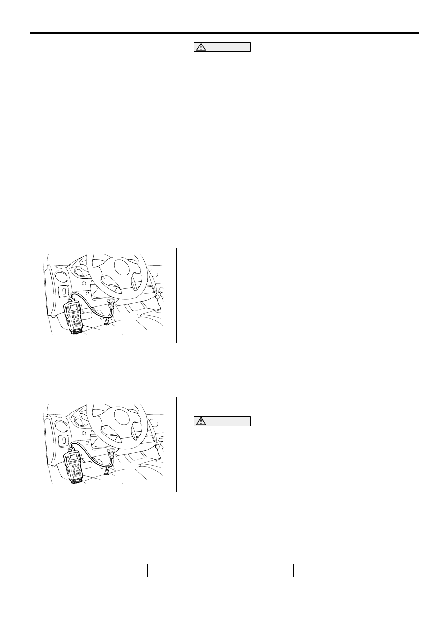
CAUTION
To prevent damage to scan tool MB991502, always turn the
ignition switch to the "LOCK" (OFF) position before
connecting or disconnecting scan tool MB991502.
NOTE: When mode II is selected with MUT-II, the Service
Engine Soon/Malfunction Indicator Lamp will light when the
engine control module (ECM) <M/T> or powertrain control
module (PCM) <A/T> first detects the trouble (Note that this is
only for emission-related trouble). At the same time, the
relevant diagnostic trouble codes will be registered. In respect
to the comprehensive component electrical faults (opens/
shorts), the time for the diagnostic trouble code to be registered
after the fault occurrence is four seconds
→
one second.
Therefore, the confirmation of the trouble symptom and the
confirmation after completing repairs can be reduced. To return
to the normal mode I after mode II has been selected once, the
ignition switch must be turned "OFF" once or mode I must be
reselected with MUT-II. The diagnostic trouble code, readiness
test status and freeze frame data, etc., will be erased when
mode I is returned to, so record these before returning to mode
I.
1. Connect scan tool MB991502 to the data link connector.
2. Turn the ignition switch to the "ON" position.
3. Change the diagnostic test mode of the ECM <M/T> or PCM
<A/T> to DIAGNOSTIC TEST MODE II (INCREASED
SENSITIVITY).
4. Road test the vehicle.
5. Read the diagnostic trouble code and repair the
malfunctioning part.
6. Turn the ignition switch to the "LOCK" (OFF) position.
7. Disconnect scan tool MB991502 from the data link
connector.
INSPECTION USING SCAN TOOL MB991502,
DATA LIST AND ACTUATOR TESTING
Required Special Tool:
MB991502: Scan Tool (MUT-II)
CAUTION
To prevent damage to scan tool MB991502, always turn the
ignition switch to the "LOCK" (OFF) position before
connecting or disconnecting scan tool MB991502.
1. Connect scan tool MB991502 to the data link connector.
2. Turn the ignition switch to the "ON" position.
3. Carry out inspection by means of the data list and the
actuator test function. If there is an abnormality, check and
repair the chassis harnesses and components. Refer to
Data List Reference Table (
Refer to Actuator Test Reference Table (
4. Re-check using scan tool MB991502 and check to be sure
that the abnormal input and output have returned to normal
because of the repairs.
AKX01177
16 PIN
MB991502
AB
AKX01177
16 PIN
MB991502
AB
Нет комментариевНе стесняйтесь поделиться с нами вашим ценным мнением.
Текст