Mitsubishi Eclipse / Eclipse Spyder (2000-2002). Service and repair manual — part 570
ON-VEHICLE SERVICE
TSB Revision
BASIC BRAKE SYSTEM
35A-29
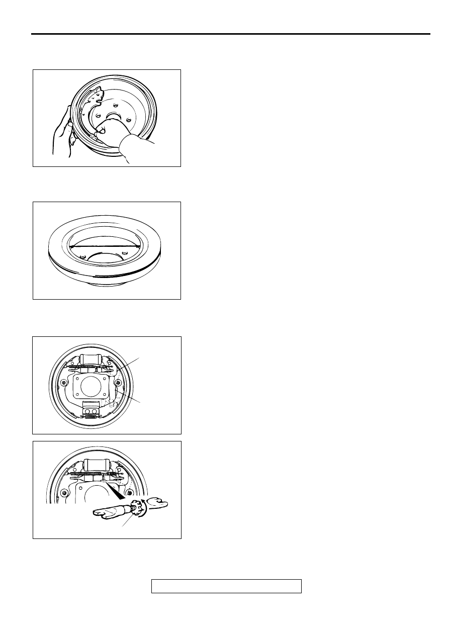
BRAKE LINING AND BRAKE DRUM CONTACT
CHECK
M1351003100063
1. Remove the brake drum.
2. Remove the shoe and lining assembly. (Refer to
.)
3. Chalk the inner surface of the brake drum and rub with the
shoe and lining assembly.
4. Replace the shoe and lining assembly or brake drums if
there are any irregular contact areas.
NOTE: Clean off chalk after check.
BRAKE DISC INSIDE DIAMETER CHECK
M1351003200112
1. Remove the rear brake assembly, raise the rear brake
assembly and secure it with a wire, etc.
2. Remove the brake disc.
3. Measure the inside diameter of the hub and disc at two or
more locations.
Standard value: 168.0 mm (6.61 inches)
Limit: 169.0 mm (6.65 inches)
4. Replace the brake discs and shoe and lining assembly when
the wear exceeds the limit value or if the measured areas
are not equal to each other. (concentric).
AUTO ADJUSTER FUNCTION CHECK
M1351010100065
1. Remove the brake drum.
2. Operate the parking brake lever. Observe adjuster lever
movement for ratcheting action of the auto adjuster. Repair
or replace the lever(s) as required.
3. Remove the shoe-to-lever spring.
4. Remove the adjuster.
NOTE: It may be necessary to rotate the adjuster wheel
bottom to top to release tension.
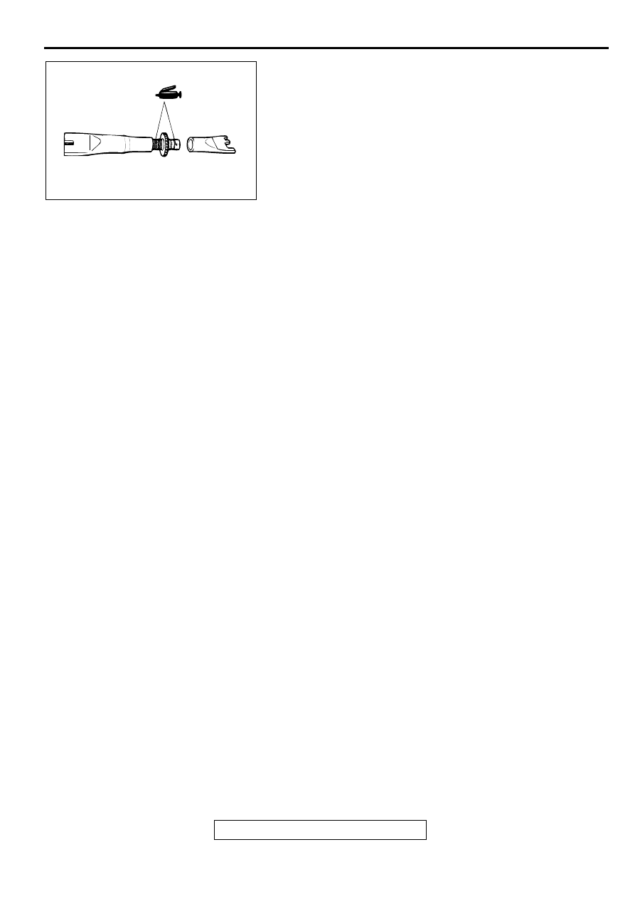
5. Inspect the adjuster wheel for wear, i.e., flat spots, worn
teeth, etc. Replace if faulty.
6. Check both ends of the adjuster for smooth rotation.
Replace if faulty.
AC000856
ACX00709AB
AC000894
ADJUSTER
LEVER
PARKING
BRAKE
LEVER
AB
AC000895 AB
ADJUSTER WHEEL
ON-VEHICLE SERVICE
TSB Revision
BASIC BRAKE SYSTEM
35A-30
7. Apply brake grease SAE J310, NLGI number 1 as shown.
8. To install adjuster, assemble the adjuster so it is at its
minimum length and insert between shoe and lining
assemblies.
9. Install adjuster lever and shoe-to-lever spring.
10.Rotate the adjuster wheel top to bottom until the drum has a
slight drag when the drum is installed.
MASTER CYLINDER FUNCTION CHECK
M1351010200062
1. Remove the reservoir cap and diaphragm.
2. While watching the open reservoir from a distance of 50 cm
(20 inches), have an assistant depress the brake pedal.
If there was a stream of brake fluid rising from the reservoir,
proceed to Step 3.
If there was no stream of brake fluid rising from the
reservoir, repair or replace the master cylinder.
3. While watching the open reservoir from a distance of 50 cm
(20 inches), have the assistant release the brake pedal.
If there was a small amount of air bubbles rising through the
brake fluid, master cylinder function is normal.
If there were no bubbles rising through the brake fluid, repair
or replace the master cylinder.
AC000896
BRAKE PEDAL
TSB Revision
BASIC BRAKE SYSTEM
35A-31
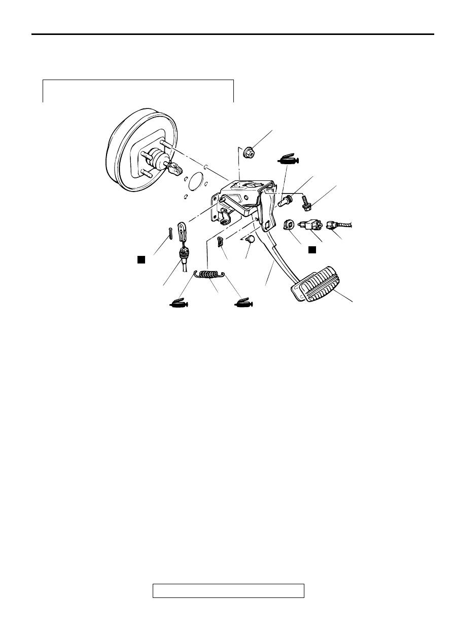
B R A K E PED A L
REMOVAL AND INSTALLATION
M1351003400075
Post-installation Operation
•
Brake Pedal Adjustment (Refer to
AC000897
14 ± 3 N·m
124 ± 26 in-lb
12 ± 2 N·m
102 ± 22 in-lb
6
N
2
1
3
10
11
5
4
9
8
7
N
AB
REMOVAL STEPS
1. HARNESS CONNECTOR
2. STOPLIGHT SWITCH
3. ADJUSTER
4. PEDAL STOPPER
5. SNAP PIN
6. CLEVIS PIN
7. COTTER PIN <A/T>
8. SHIFT LOCK CABLE CONNECTION
<A/T>
9. RETURN SPRING
10. PEDAL PAD
11. BRAKE PEDAL AND PEDAL
SUPPORT MEMBER ASSEMBLY
REMOVAL STEPS (Continued)
MASTER CYLINDER ASSEMBLY AND BRAKE BOOSTER
TSB Revision
BASIC BRAKE SYSTEM
35A-32
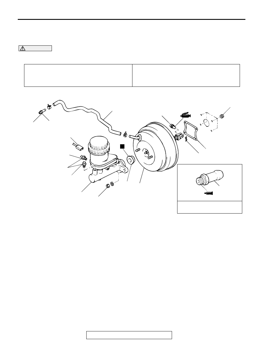
M A STER C YLIN DER ASSEM B LY AN D B R A K E B O O STER
REMOVAL AND INSTALLATION
M1351003700065
CAUTION
Do not remove the check valve from the vacuum hose. If the check valve is defective, replace it
together with the vacuum hose.
Pre-removal Operation
•
Brake Fluid Draining
Post-installation Operation
•
Brake Fluid Supplying
•
Brake Line Bleeding (Refer to
.)
•
Brake Pedal Adjustment (Refer to
.)
AC004248
17 ± 1 N·m
12 ± 1 ft-lb
5
4
2
1
1
15 ± 2 N·m
11 ± 1 ft-lb
3
10
8
N
7
6
9
14 ± 3 N·m
122 ± 26 in-lb
9.8 ± 2.0 N·m*¹
87 ± 17 in-lb*¹
13 ± 3 N·m*²
113 ± 26 in-lb*²
5
SEALANT: 3M™ AAD PART
NO. 8663 OR EQUIVALENT
AB
NOTE
*1: VEHICLES WITHOUT TCL
*2: VEHICLES WITH TCL
REMOVAL STEPS
1. BRAKE TUBE CONNECTION
2. BRAKE FLUID LEVEL SENSOR
CONNECTOR
3. MASTER CYLINDER ASSEMBLY
>>B<<
•
ADJUSTMENT OF CLEARANCE
BETWEEN BRAKE BOOSTER
PUSHROD AND PRIMARY PISTON
>>A<<
4. VACUUM HOSE (WITH BUILT-IN
CHECK VALVE)
5. FITTING
6. SNAP PIN
7. CLEVIS PIN
•
STRUT TOWER BAR ASSEMBLY
<VEHICLES WITH STRUT TOWER
BAR> (REFER TO GROUP 42,
STRUT TOWER BAR
8. BRAKE BOOSTER
9. SEALER
10. PLATE AND SEAL ASSEMBLY
<VEHICLES WITH TCL>
REMOVAL STEPS (Continued)
Нет комментариевНе стесняйтесь поделиться с нами вашим ценным мнением.
Текст