Mitsubishi Eclipse / Eclipse Spyder (2000-2002). Service and repair manual — part 325
MULTIPORT FUEL INJECTION (MFI) DIAGNOSIS
TSB Revision
MULTIPORT FUEL INJECTION (MFI) <3.0L ENGINE>
13B-499
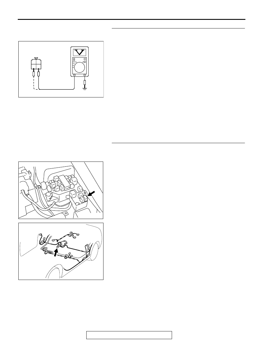
STEP 7. Check the power supply voltage at fuel pump relay
connector A-20X.
(1) Disconnect the connector A-20X and measure at the
harness side.
(2) Turn the ignition switch to the "ON" position.
(3) Measure the voltage between terminal 3, 4 and ground.
•
Voltage should be battery positive voltage.
(4) Turn the ignition switch to the "LOCK" (OFF) position.
Q: Is the voltage normal?
YES : Go to Step 8.
NO : Check harness connectors C-07, C-89 and C-101 at
intermediate connector for damage, and repair or
replace as required. Refer to, GROUP 00E, Harness
Connector Inspection (
). If intermediate
connectors are in good condition, repair harness wire
between ignition switch connector C-87 terminal 2
and fuel pump relay connector A-20X terminal 3, 4
because of open circuit. Then confirm that the
malfunction symptom is eliminated.
STEP 8. Check for open circuit and short circuit to ground
and harness damage between fuel pump relay connector
A-20X terminal 1 and fuel pump connector D-17 terminal 5.
NOTE: Check harness after checking intermediate connectors
C-28 and C-90. If intermediate connectors are damaged, repair
or replace them. After to GROUP 00E, Harness Connector
Inspection (
). Then check that the malfunction is
eliminated.
Q: Is the harness wire in good condition?
YES : Go to Step 9.
NO : Repair it. Then confirm that the malfunction symptom
is eliminated.
AKX01441
A-20X HARNESS
SIDE CONNECTOR
1
2
3
4
AC
AK000360AB
CONNECTOR : A-20X
AK000734AC
CONNECTOR:D-17
MULTIPORT FUEL INJECTION (MFI) DIAGNOSIS
TSB Revision
MULTIPORT FUEL INJECTION (MFI) <3.0L ENGINE>
13B-500
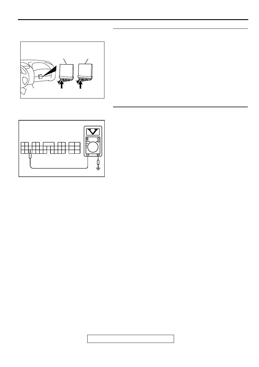
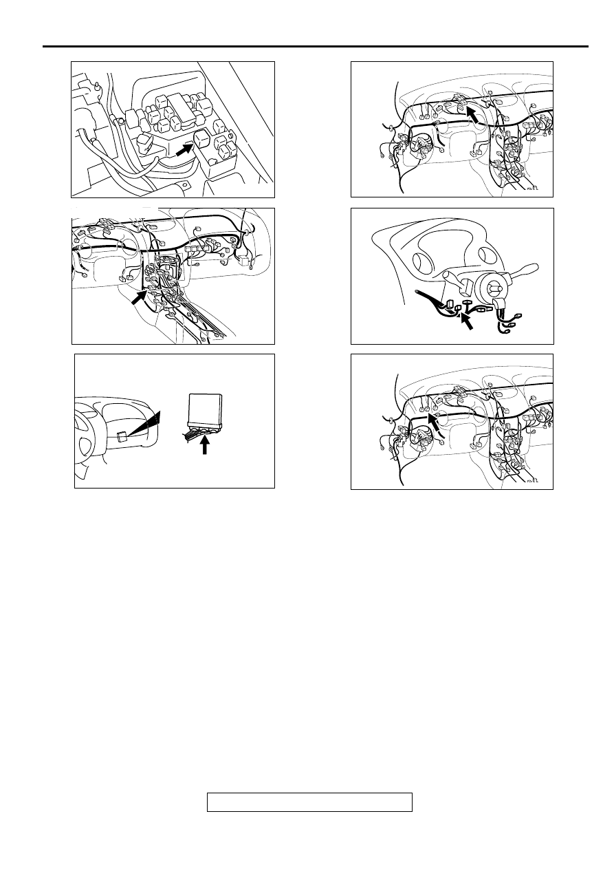
STEP 9. Check connector C-51 at ECM <M/T> or connector
C-52 at PCM <A/T> for damage.
Q: Is the connector in good condition?
YES : Go to Step 10.
NO : Repair or replace it. Refer to GROUP 00E, Harness
Connector Inspection (
). Then confirm that
the malfunction symptom is eliminated.
STEP 10. Check the power supply voltage at ECM
connector C-51 <M/T> or PCM connector C-52 <A/T>.
(1) Disconnect the connector C-51 <M/T> or C-52 <A/T> and
measure at the harness side.
(2) Turn the ignition switch to the "ON" position.
(3) Measure the voltage between terminal 21 and ground.
•
Voltage should be battery positive voltage.
(4) Turn the ignition switch to the "LOCK" (OFF) position.
Q: Is the voltage normal?
YES : Replace the ECM or PCM. Then confirm that the
malfunction symptom is eliminated.
NO : Repair harness wire between fuel pump relay
connector A-20X terminal 2 and ECM connector C-51
terminal 21 <M/T> or PCM connector C-52 terminal
21 <A/T> because of open circuit. Then confirm that
the malfunction symptom is eliminated.
AK000225
CONNECTOR : C-51<M/T>, C-52<A/T>
C-52
C-51
PCM<A/T>
ECM<M/T>
AJ
AK000448AC
8 7
6 5
4 3
2
1
9
10
11
12
13
14
15
16
17
18
19
20
21
22
23
24
25
26
27
28
30
31
32
33
34
35
29
C-51<M/T>,C-52<A/T>
HARNESS SIDE
CONNECTOR
MULTIPORT FUEL INJECTION (MFI) DIAGNOSIS
TSB Revision
MULTIPORT FUEL INJECTION (MFI) <3.0L ENGINE>
13B-501
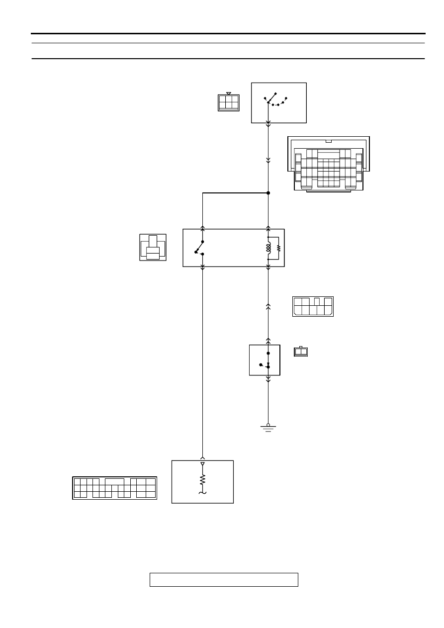
INSPECTION PROCEDURE 31: Ignition Switch-ST System. <M/T>
AK000718
3
4
5
4 5 6
1 2 3
1
BL
ACK
-
RED
BL
ACK
-
RED
BL
ACK
-
RED
BL
ACK
-
RED
2
8
7
2
6
3
5
1
BL
ACK
-RED
4
BL
ACK
GREEN-
BL
ACK
GREEN-
BL
ACK
A-18X
4
2
3
1
STARTER
RELAY
LOCK
ACC
C-87
R
IGNITION
SWITCH
IG2
IG1
ST
5
C-58
(MU803782)
68
16
4
2
INTERLOCK
SWITCH
C-02
1
OFF
ON
ENGINE
CONTROL
MODULE(ECM)
C-07
MU801333
C-28
7 8
5
3 4
35
34
10 11 12
2122 23 24
13 14 15
25 26 27
16
28
17
18 19 20
29
30 31
32 33
36 37
38
9
1 2
6
65
43
50
42
49
41
48
60 61
64
46 47
58 59
67 68
45
56
66
52
51
44
53
62
54
63
57
55
1 2
MULTIPORT FUEL INJECTION (MFI) DIAGNOSIS
TSB Revision
MULTIPORT FUEL INJECTION (MFI) <3.0L ENGINE>
13B-502
CIRCUIT OPERATION
•
The battery positive voltage is supplied to the
ECM (terminal 68) via the starter relay during
engine cranking. With this, the ECM detects that
the engine is being cranked.
TROUBLESHOOTING HINTS (The most likely
causes for this case:)
•
Malfunction of the ignition switch.
•
Malfunction of the starter relay.
•
Improper connector contact, open circuit or short-
circuited harness wire.
•
Malfunction of the ECM.
AK000356
CONNECTOR : A-18X
AB
AK000733AC
CONNECTOR:C-28
AK000357
CONNECTOR:C-58
AD
AK000312AJ
CONNECTOR:C-07
AK000219
CONNECTOR:C-87
AC
AK000312AF
CONNECTOR : C-02
Нет комментариевНе стесняйтесь поделиться с нами вашим ценным мнением.
Текст