Mitsubishi Colt Ralliart. Manual — part 108

WATER PUMP
ENGINE COOLING
14-14
REMOVAL AND INSTALLATION <4G1>
M1141002700841
Pre-removal Operation
• Engine Coolant Draining (Refer to
).
• Valve Timing Belt Removal (Refer to GROUP 11C, Timing
Belt
Post-installation Operation
• Valve Timing Belt Installation (Refer to GROUP 11C, Tim-
).
• Engine Coolant Refilling (Refer to
).
AC402117
AC402116
AC402524AB
1
24 ± 3 N·m
14 ± 1 N·m
2
23 ± 2 N·m
8 × 30
8 × 50
8 × 20
2
8 × 30
8 × 20
8 × 20
Bolt specifications
Screw diameter × length mm
Removal steps
>>
B
<<
1.
Alternator brace
>>
A
<<
2.
Water pump
INSTALLATION SERVICE POINTS
>>A<< WATER PUMP INSTALLATION
Check that the O-ring on the reverse side of water
pump has not fallen out, and then install the water
pump on the cylinder block.
>>B<< ALTERNATOR BRACE
INSTALLATION
AC403625AB
Nut
Install the alternator brace nut so that it is in the
direction shown.
Main
Index
Group
TOC
WATER HOSE AND WATER PIPE
ENGINE COOLING
14-15
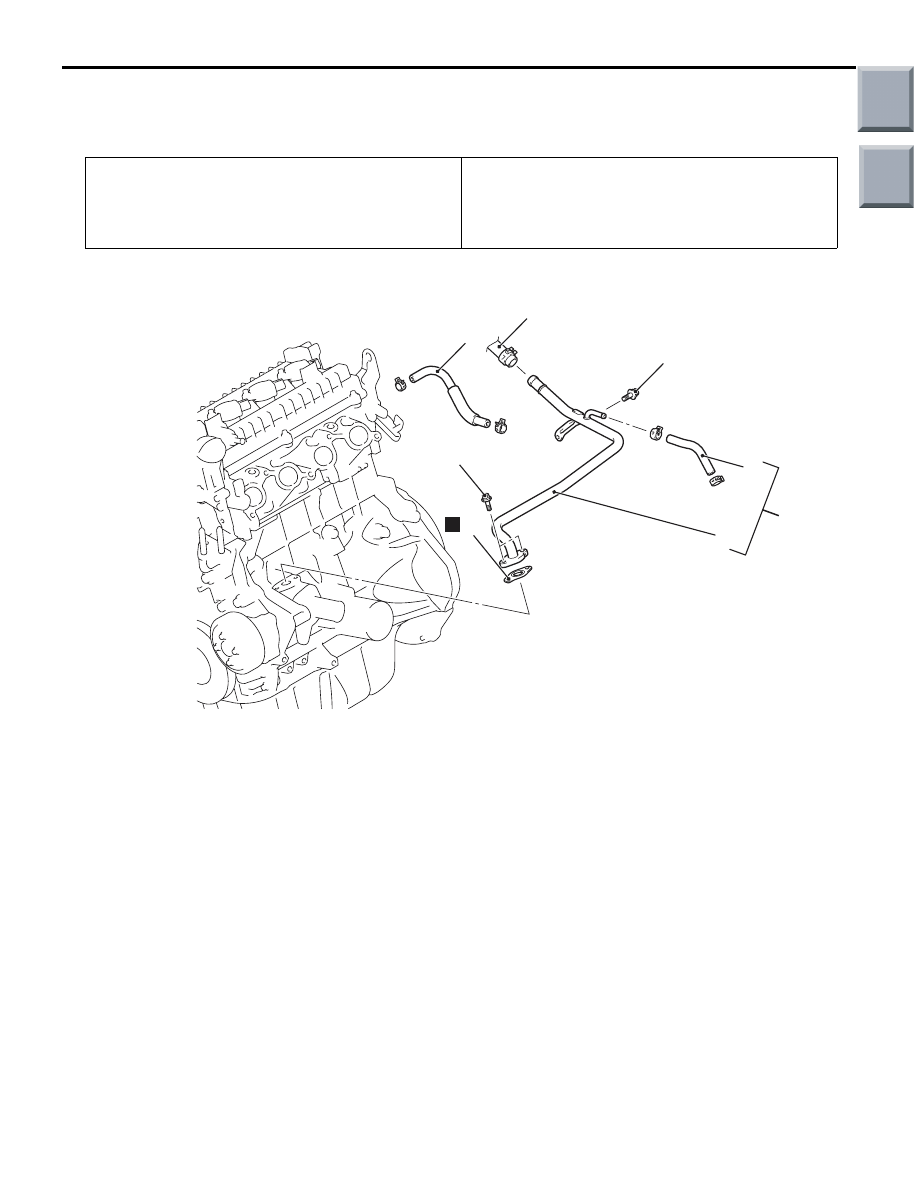
WATER HOSE AND WATER PIPE
REMOVAL AND INSTALLATION <4A9>
M1141003301322
Pre-removal Operation
• Inlet Manifold Removal (Refer to GROUP 15, Inlet Mani-
).
Post-installation Operation
• Inlet Manifold Installation (Refer to GROUP 15, Inlet Man-
ifold
).
• Engine Oil Check <CVT> (Refer to GROUP 12, On-vehi-
cle Service
− Engine Oil Check
<M/T>
AC601297AB
4
N
5
6
3
7.6 ± 0.6 N·m
7.6 ± 0.6 N·m
1
2
Removal steps
>>
A
<<
1.
Throttle body water feed hose
2.
Heater piping hose connection
3.
Throttle body water return hose and
water pump inlet pipe assembly
>>
B
4.
Gasket
>>
A
5.
Throttle body water return hose
6.
Water pump inlet pipe
Removal steps (Continued)
Main
Index
Group
TOC
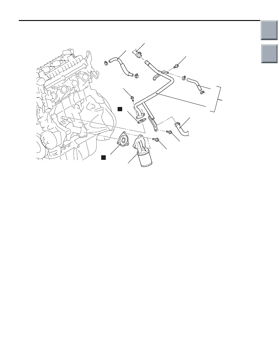
WATER HOSE AND WATER PIPE
ENGINE COOLING
14-16
<CVT>
AC402407AB
5
N
4
20 ± 1 N·m
7
N
3
8
9
6
7.6 ± 0.6 N·m
7.6 ± 0.6 N·m
1
2
20 ± 1 N·m
Removal steps
>>
A
<<
1.
Throttle body water feed hose
2.
Heater piping hose connection
3.
Water hose connection
4.
Oil filter and bracket assembly
>>
C
<<
5.
Gasket
6.
Throttle body water return hose and
water pump inlet pipe assembly
>>
B
7.
Gasket
>>
A
8.
Throttle body water return hose
9.
Water pump inlet pipe
Removal steps (Continued)
Main
Index
Group
TOC
WATER HOSE AND WATER PIPE
ENGINE COOLING
14-17
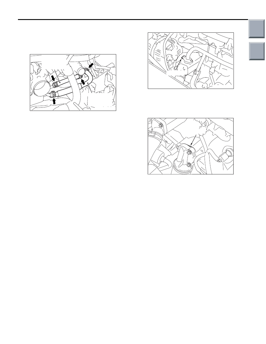
INSTALLATION SERVICE POINTS
>>A<< THROTTLE BODY WATER
RETURN HOSE/THROTTOLE BODY
WATER FEED HOSE INSTALLATION
AC403642AB
Throttle body
water return
hose
Throttle body
water feed
hose
Install the hose clips as shown.
>>B<< GASKET INSTALLATION
AC403643AB
Projection
Install the gasket as its protrusion is in the direction
shown.
>>C<< GASKET INSTALLATION
AC402978AB
Projection
Install the gasket as its protrusion is in the direction
shown.
Main
Index
Group
TOC
Нет комментариевНе стесняйтесь поделиться с нами вашим ценным мнением.
Текст