Mitsubishi Colt Ralliart. Manual — part 348

SYMPTOM PROCEDURES
SMART WIRING SYSTEM (SWS) NOT USING SWS MONITOR
54B-136
DIAGNOSIS PROCEDURE
Step 1. Pulse check
Check the input signal from the tail lamp switch.
OK: The M.U.T.-III sounds or the voltmeter
needle fluctuates.
Q: Is the check result normal?
All the signals are received normally. :
Go to Step
2.
The ignition switch (IG1) signal is not received. :
Refer to Inspection Procedure N-2 "The
ignition switch (IG1) signal is not received
."
The tail lamp switch signal is not received. :
Refer
to Inspection Procedure N-4 "The column
switch (lighting and turn-signal lamp) signal
is not received
."
Step 2. Connector check: B-134 ETACS-ECU
connector.
Q: Is the check result normal?
YES :
Go to Step 3.
NO :
Repair the defective connector.
Step 3. Voltage measurement at B-134
ETACS-ECU connector.
(1) Remove the ETACS-ECU, and measure at the
junction block side.
(2) Voltage between B-134 ETACS-ECU connector
terminal No.16 and body earth
OK: System voltage
Q: Is the check result normal?
YES :
Go to Step 5.
NO :
Go to Step 4.
System switch
Check condition
Ignition switch (IG1)
When turned from ACC
to ON
Tail lamp switch
When the lighting switch
is turned to the TAIL
position
AC313872 AH
Connector: B-134
Harness side
Junction block (Rear view)
AC313872 AH
Connector: B-134
Harness side
Junction block (Rear view)
AC313972
Connector B-134
(Harness side)
AT
Main
Index
Group
TOC

SYMPTOM PROCEDURES
SMART WIRING SYSTEM (SWS) NOT USING SWS MONITOR
54B-137
Step 4. Check the wiring harness between B-134
ETACS-ECU connector terminal No.16 and the
fusible link (1).
NOTE:
Prior to the wiring harness inspection, check junction
block connector B-108, and repair if necessary.
• Check the power supply line for open circuit.
Q: Is the check result normal?
YES :
The trouble can be an intermittent
malfunction (Refer to GROUP 00
− How to
use Troubleshooting/inspection Service
Points
− How to Cope with Intermittent
).
NO :
Repair the wiring harness.
Step 5. Retest the system.
Check that the tail lamps illuminate normally.
Q: Is the check result normal?
YES :
The trouble can be an intermittent
malfunction (Refer to GROUP 00
− How to
use Troubleshooting/inspection Service
Points
− How to Cope with Intermittent
).
NO :
Replace the ETACS-ECU.
AC313872 AH
Connector: B-134
Harness side
Junction block (Rear view)
AC313870
Connector: B-108
BD
Junction block (Front view)
B-108(B)
Harness side
Main
Index
Group
TOC
SYMPTOM PROCEDURES
SMART WIRING SYSTEM (SWS) NOT USING SWS MONITOR
54B-138
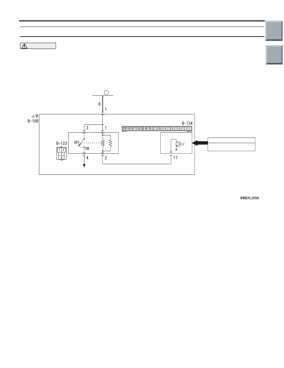
INSPECTION PROCEDURE J-2: The low-beam headlamps do not illuminate normally.
CAUTION
Whenever the ECU is replaced, ensure that the
input and output signal circuits are normal.
COMMENTS ON TROUBLE SYMPTOM
If the low-beam headlamps do not illuminate, the
headlamp switch input circuit, the headlamp relay
(LO) or the ETACS-ECU may be defective. If the
SWS monitor ECU check shows "NG", also check
the headlamp backup circuit (from column switch
connector terminal No.10 to ETACS-ECU connector
terminal No.60) and repair if necessary.
POSSIBLE CAUSES
• Malfunction of the headlamp relay (LO)
• Malfunction of the column switch
• Malfunction of the ETACS-ECU
• Damaged harness wires and connectors
Wire colour code
B : Black LG : Light green G : Green L : Blue W : White Y : Yellow SB : Sky blue
BR : Brown O : Orange GR : Gray R : Red P : Pink V : Violet
ETACS-ECU
HEADLAMP
RELAY (LO)
HAEDLAMP
FUSIBLE
LINK
1
HEADLAMP SWITCH
INPUT SIGNAL
J/B SIDE
Headlamp Relay (Low-Beam) Circuit
Main
Index
Group
TOC

SYMPTOM PROCEDURES
SMART WIRING SYSTEM (SWS) NOT USING SWS MONITOR
54B-139
DIAGNOSTIC PROCEDURE
Step 1. Pulse check
Check the input signal from the headlamp switch.
OK: The M.U.T.-III sounds or the voltmeter
needle fluctuates.
Q: Are the check result normal?
All the signals are received normally. :
Go to Step
2.
The ignition switch (IG1) signal is not received. :
Refer to Inspection Procedure N-2 "The
ignition switch (IG1) signal is not received
."
The headlamp switch signal is not received. :
Refer to Inspection Procedure N-4 "The
column switch (lighting and turn-signal lamp
switch) signal is not received
Step 2. Connector check: B-123 headlamp relay
(LO) connector
Q: Is the check result normal?
YES :
Go to Step 3.
NO :
Repair the defective connector.
Step 3. Check the headlamp relay (LO).
Refer to GROUP 54A
− Headlamp
Q: Is the check result normal?
YES :
Go to Step 4.
NO :
Replace the headlamp relay (LO).
Step 4. Voltage measurement at B-123 headlamp
relay (LO) connector.
(1) Remove the headlamp relay (LO), and measure
at the junction block side.
(2) Voltage between B-123 headlamp relay (LO)
connector terminal Nos.1, 3 and body earth
OK: System voltage
Q: Is the check result normal?
YES :
Go to Step 6.
NO :
Go to Step 5.
System switch
Check condition
Ignition switch (IG1)
When turned from ACC
to ON
Headlamp switch
When the lighting switch
is turned to the HEAD
position
AC313870 AD
Connector: B-123
Junction Block (Front view)
Harness side
AC313870 AD
Connector: B-123
Junction Block (Front view)
Harness side
AC313972AV
Connector B-123
(Harness side)
Main
Index
Group
TOC
Нет комментариевНе стесняйтесь поделиться с нами вашим ценным мнением.
Текст