Mitsubishi Colt Ralliart. Manual — part 40
TROUBLESHOOTING
MULTIPORT FUEL INJECTION (MPI) <4A9>
13A-114
DIAGNOSIS PROCEDURE
STEP 1. M.U.T.-III data list
• Refer to Data List Reference Table
.
a. Item 14: Throttle position sensor (sub)
Q: Is the check result normal?
YES :
Intermittent malfunction (Refer to GROUP
00
− How to Use
Troubleshooting/Inspection Service Points
−
How to Cope with Intermittent Malfunctions
).
NO :
Go to Step 2 .
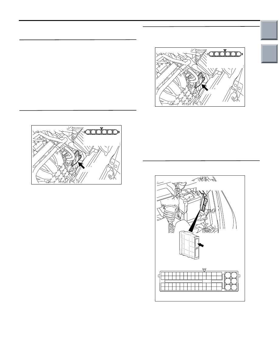
STEP 2. Connector check: A-107
electronic-controlled throttle valve connector
Q: Is the check result normal?
YES :
Go to Step 3 .
NO :
Repair or replace the connector.
STEP 3. Perform resistance measurement at
A-107 electronic-controlled throttle valve
connector.
• Disconnect connector, and measure at harness
side.
• Resistance between terminal No. 3 and earth.
OK: Continuity (2
Ω or less)
Q: Is the check result normal?
YES :
Go to Step 7 .
NO :
Go to Step 4 .
STEP 4. Connector check: A-114 engine-ECU
connector or engine-CVT-ECU connector
Q: Is the check result normal?
YES :
Go to Step 5 .
NO :
Repair or replace the connector.
AK402006
1
6 5 4 3 2
AC
A-107 (B)
Connector: A-107
A-107 Harness side
connector
AK402006
1
6 5 4 3 2
AC
A-107 (B)
Connector: A-107
A-107 Harness side
connector
AK402745
6
4
2
5
3
1
9
7
8
10
11
12
13
14
15
16
17
18
19
20
21
22
23
24
25
26
27
28
29
30
31
32
33
34
35
36
37
38
39
40
41
42
43
44
45
46
47
48
49
50
51
52
53
54
55
56
57
58
59
60
61
62
63
64
65
66
L
AD
A-114
Connector:
A-114
Harness side connector
Engine-ECU <M/T> or
engine-CVT-ECU <CVT>
Battery
Main
Index
Group
TOC
TROUBLESHOOTING
MULTIPORT FUEL INJECTION (MPI) <4A9>
13A-115
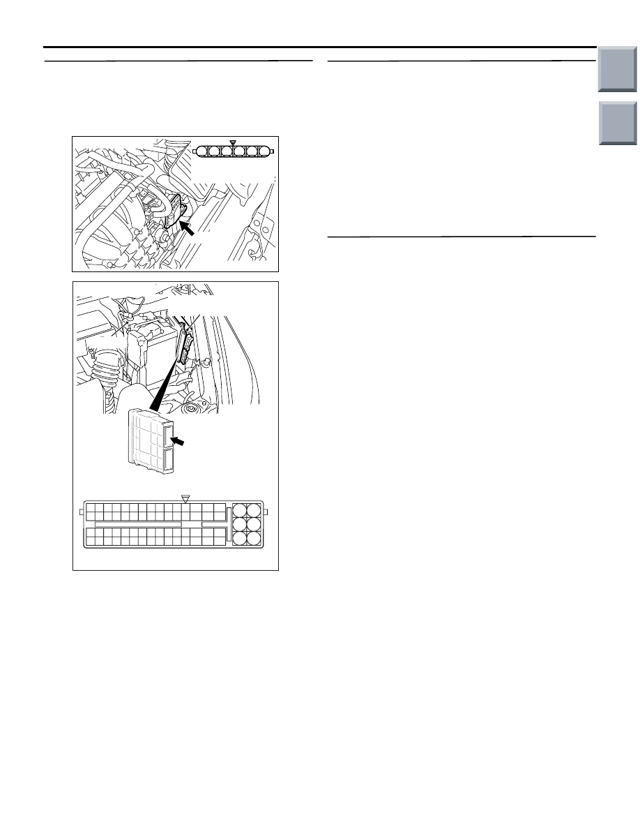
STEP 5. Check harness between A-107 (terminal
No. 3) electronic-controlled throttle valve
connector and A-114 (terminal No. 30)
engine-ECU connector or engine-CVT-ECU
connector.
• Check earthing line for open circuit and damage.
Q: Is the check result normal?
YES :
Go to Step 6 .
NO :
Repair the damaged harness wire.
STEP 6. M.U.T.-III data list
• Refer the to Data List Reference Table
.
a. Item 14: Throttle position sensor (sub)
Q: Is the check result normal?
YES :
Intermittent malfunction (Refer to GROUP
00
− How to Use Troubleshooting/Inspection
Service Points
− How to Cope with
Intermittent Malfunctions
).
NO :
Replace the engine-ECU <M/T> or
engine-CVT-ECU <CVT>.
STEP 7. Replace the throttle body assembly
• After replacing the throttle body assembly,
re-check the trouble symptoms.
Q: Is the check result normal?
YES :
Check end.
NO :
Replace the engine-ECU <M/T> or
engine-CVT-ECU <CVT>.
AK402006
1
6 5 4 3 2
AC
A-107 (B)
Connector: A-107
A-107 Harness side
connector
AK402745
6
4
2
5
3
1
9
7
8
10
11
12
13
14
15
16
17
18
19
20
21
22
23
24
25
26
27
28
29
30
31
32
33
34
35
36
37
38
39
40
41
42
43
44
45
46
47
48
49
50
51
52
53
54
55
56
57
58
59
60
61
62
63
64
65
66
L
AD
A-114
Connector:
A-114
Harness side connector
Engine-ECU <M/T> or
engine-CVT-ECU <CVT>
Battery
Main
Index
Group
TOC

TROUBLESHOOTING
MULTIPORT FUEL INJECTION (MPI) <4A9>
13A-116
Code No. P0300: Random/Multiple Cylinder Misfire Detected
OPERATION
• Refer to Code No. P0201: No. 1 injector system
• Refer to Code No. P0202: No. 2 injector system
• Refer to Code No. P0203: No. 3 injector system
• Refer to Code No. P0204: No. 4 injector system
.
FUNCTION
• If a misfire occurs while the engine is running, the
engine speed changes for an instant.
• The engine-ECU <M/T> or engine-CVT-ECU
<CVT> checks for such changes in engine
speed.
TROUBLE JUDGMENT
Check Conditions
• Engine speed is 500 − 4,500 r/min.
• Engine coolant temperature is −10°C or higher.
• The intake manifold pressure is above 30 kPa
<M/T>.
• Barometric pressure is 76 kPa or higher <CVT>
• Volumetric efficiency is between 30 % and 55 %
<CVT>.
• Adaptive learning is complete for the vane which
generates a crankshaft position signal.
• While the engine is running, excluding gear shift-
ing, deceleration, sudden acceleration/decelera-
tion and A/C compressor switching.
• The throttle deviation is −0.06 V/10 ms to +0.06
V/10 ms.
Judgment Criteria (change in the angular accel-
eration of the crankshaft is used for misfire
detection).
• Misfire has occurred more frequently than the
limit during the last 200 revolutions (when the cat-
alyst temperature has been 950
°C or higher).
or
• Misfire has occurred 15 times or more in the last
1,000 revolutions (that has been equivalent to
approximately 1.5 times the emission standard).
PROBABLE CAUSES
• Ignition system related part(s) failed
• Failed crank angle sensor
• Incorrect air-fuel ratio
• Low compression pressure
• Failed engine coolant temperature sensor
• Skipping of timing belt teeth.
• EGR system and EGR valve failed <CVT>
• Failed engine-ECU <M/T> or engine-CVT-ECU
<CVT>
DIAGNOSIS PROCEDURE
STEP 1. M.U.T.-III data list
• Item 22: Crank angle sensor
OK: Keep the engine speed constant to make
the pulse width of output waveform con-
stant.
Q: Is the check result normal?
YES :
Go to Step 2 .
NO :
Check crank angle sensor system (Refer to
Code No. P0
STEP 2. M.U.T.-III data list
• Refer to Data List Reference Table
.
a. Item 21: Engine coolant temperature sensor
b. Item 81: Long-term fuel compensation
c. Item 82: Short-term fuel compensation
Q: Are the check results normal?
YES :
Go to Step 3 .
NO :
Perform the diagnosis code classified check
procedure for the sensor that has shown an
abnormal data valve (Refer to Inspection
Chart for Diagnosis Code
STEP 3. Visual check of ignition spark.
• Remove the spark plug and install it to the ignition
coil.
• Connect the ignition coil connector.
• Remove all injector connector.
• At the engine start, check each spark plug pro-
duces a spark.
Q: Is the check result normal?
YES :
Go to Step 4 .
NO :
Check ignition circuit system (Refer to
Inspection Procedure 28
Main
Index
Group
TOC
TROUBLESHOOTING
MULTIPORT FUEL INJECTION (MPI) <4A9>
13A-117
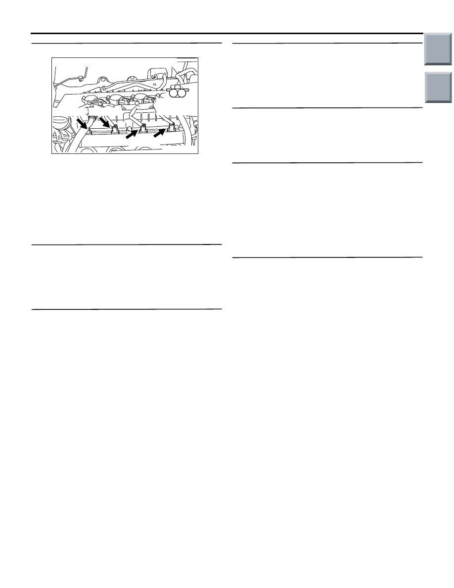
STEP 4. Connector check: Injector connector
a. A-102 (No. 1 injector connector)
b. A-103 (No. 2 injector connector)
c. A-104 (No. 3 injector connector)
d. A-105 (No. 4 injector connector)
Q: Are the check results normal?
YES :
Go to Step 5 .
NO :
Repair or replace.
STEP 5. Check injector itself.
• Check Injector itself (Refer to
Q: Is the check result normal?
YES :
Go to Step 6 .
NO :
Replace injector.
STEP 6. Fuel pressure measurement.
• Fuel pressure measurement (Refer to Fuel Pres-
sure Test
Q: Is the check result normal?
YES :
Go to Step 7 .
NO :
Repair.
STEP 7. Check for intake of air from intake hose
and inlet manifold.
Q: Is the check result normal?
YES :
Go to Step 8 .
NO :
Repair.
STEP 8. Check for skipped timing belt teeth.
Q: Is the check result normal?
YES :
Go to Step 9 <CVT> , go to Step 10 <M/T> .
NO :
Repair.
STEP 9. Check EGR valve (stepper motor) itself.
• Check EGR valve (stepper motor) itself [Refer to
GROUP 17
− Exhaust Gas Recirculation (EGR)
System
− EGR Valve (Stepper Motor) Check
].
Q: Is the check result normal?
YES :
Go to Step 10 .
NO :
Replace EGR valve (stepper motor)
STEP 10. Check the trouble symptoms.
Q: Does trouble symptom persist?
YES :
Replace engine-ECU <M/T> or
engine-CVT-ECU <CVT>.
NO :
Intermittent malfunction (Refer to Group 00
−
How to Use Troubleshooting/Inspection
Service Points
− How to Cope with
Intermittent Malfunctions
).
AK503594
M
1
2
A-104 (G)
A-103 (G)
A-102 (G)
A-105 (G)
Connectors: A-102, A-103, A-104, A-105
Harness side
connector
AB
Main
Index
Group
TOC
Нет комментариевНе стесняйтесь поделиться с нами вашим ценным мнением.
Текст