Mitsubishi Colt Ralliart. Manual — part 639
TROUBLESHOOTING
ACTIVE STABILITY CONTROL SYSTEM (ASC)
35C-101
STEP 6. Check for wheel speed sensor as a
single unit
Refer to GROUP 35B
− Wheel speed sensor
.
Q: Is the check result normal?
YES :
Go to Step 7.
NO :
Replace the wheel speed sensor.
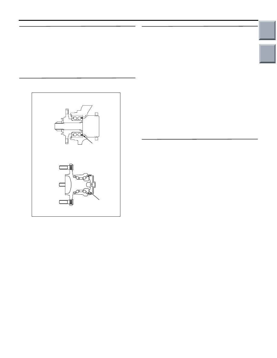
STEP 7. Wheel speed detection magnetic
encoder check
Check the wheel speed detection magnetic encoder
for adhesion of foreign materials or deformation.
NOTE: For the rear wheel speed detection magnetic
encoder, check from the mounting hole of the wheel
speed sensor by rotating the rear hub.
Q: Is the check result normal?
YES : .
Go to Step 8.
NO <Front> : .
If foreign objects are found, clean
the magnetic encoder for wheel speed
detection. When the encoder is deformed,
replace the wheel bearing. (Refer to
GROUP 26
− Front Axle Hub Assembly
.)
NO <Rear> : .
If foreign objects are found, clean
the magnetic encoder for wheel speed
detection. When the encoder is deformed,
replace the rear hub assembly. (Refer to
GROUP 27
− Rear Axle Hub Assembly
.)
STEP 8. Check the wheel bearing.
NOTE: Loose wheel bearing may increase the gap
between the wheel speed sensor and the wheel
speed detection magnet encoder. Check each wheel
bearing for looseness.
Front: Refer to GROUP 26
− On-vehicle Service
.
Rear: Refer to GROUP 27
− On-vehicle Service
.
Q: Is the check result normal?
YES :
Go to Step 9.
NO <Front> :
Replace the wheel bearing. (Refer to
GROUP 26
− Front Axle Hub Assembly
.)
NO <Rear> :
Replace the rear hub assembly.
(Refer to GROUP 27
− Rear Axle Hub
Assembly
.)
STEP 9. Retest the system.
Q: Does the stability control system operate too
frequently?
YES :
Replace the ASC-ECU.
NO :
Intermittent malfunction (Refer to GROUP
00
− How to Cope with Intermittent
.)
AC600965
<Front>
<Rear>
Encoder
AB
Encoder
Main
Index
Group
TOC
TROUBLESHOOTING
ACTIVE STABILITY CONTROL SYSTEM (ASC)
35C-102
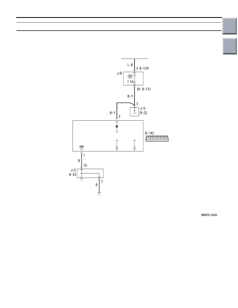
Inspection Procedure 10: Steering wheel sensor power supply system
OPERATION
The steering wheel sensor is energised by the igni-
tion switch (IG1) through the multi-purpose fuse No.
40 and the steering wheel sensor terminal No. 2.
PROBABLE CAUSES
• Damaged wiring harness and connectors
• Steering wheel sensor malfunction
Steering Wheel Sensor Power Source Circuit
Wire colour code
B : Black LG : Light green G : Green L : Blue W : White Y : Yellow SB : Sky blue
BR : Brown O : Orange GR : Grey R : Red P : Pink V : Violet PU : Purple
IGNITION
SWITCH (IG1)
STEERING
WHEEL
SENSOR
Main
Index
Group
TOC
TROUBLESHOOTING
ACTIVE STABILITY CONTROL SYSTEM (ASC)
35C-103
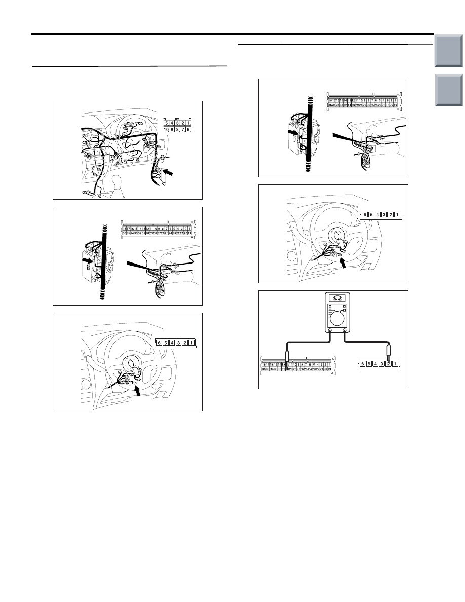
DIAGNOSTIC PROCEDURE
STEP 1. Connector inspection: B-22 joint
connector, B-131 junction block connector, B-142
steering wheel sensor connector
Q: Is the check result normal?
YES :
Go to Step 2.
NO :
Repair the damaged connector.
STEP 2. Measure the resistance between B-142
steering wheel sensor connector and B-131
junction block connector.
(1) Disconnect B-142 steering wheel sensor
connector and B-131 junction block connector.
(2) Measure the resistance between B-142 steering
wheel sensor connector terminal No. 2 and B-131
junction block connector terminal No. 30.
OK: Continuity exists (2
Ω or less)
Q: Is the check result normal?
YES :
Go to Step 4.
NO :
Go to Step 3.
AC601112
Connector: B-22
AB
B-22
Harness side
J/B
i
û
j
AC601113
J/B
(Back view)
AC601113
Connector: B-131
AB
B-131
Harness side
AC601114
Connector: B-142
AB
B-142
Harness side
J/B
i
û
j
AC601113
J/B
(Back view)
AC601113
Connector: B-131
AB
B-131
Harness side
AC601114
Connector: B-142
AB
B-142
Harness side
AC601116
B-131: Harness side
B-142: Harness side
AB
Main
Index
Group
TOC
TROUBLESHOOTING
ACTIVE STABILITY CONTROL SYSTEM (ASC)
35C-104
STEP 3. Check the wiring harness between B-142
steering wheel sensor connector terminal No. 2
and the ignition switch (IG1).
Check the power supply line for open circuit.
Q: Is the check result normal?
YES :
Intermittent malfunction (Refer to GROUP
00
− How to Cope with Intermittent
.)
NO :
Repair the wiring harness between B-142
steering wheel sensor connector terminal
No. 2 and the ignition switch (IG1).
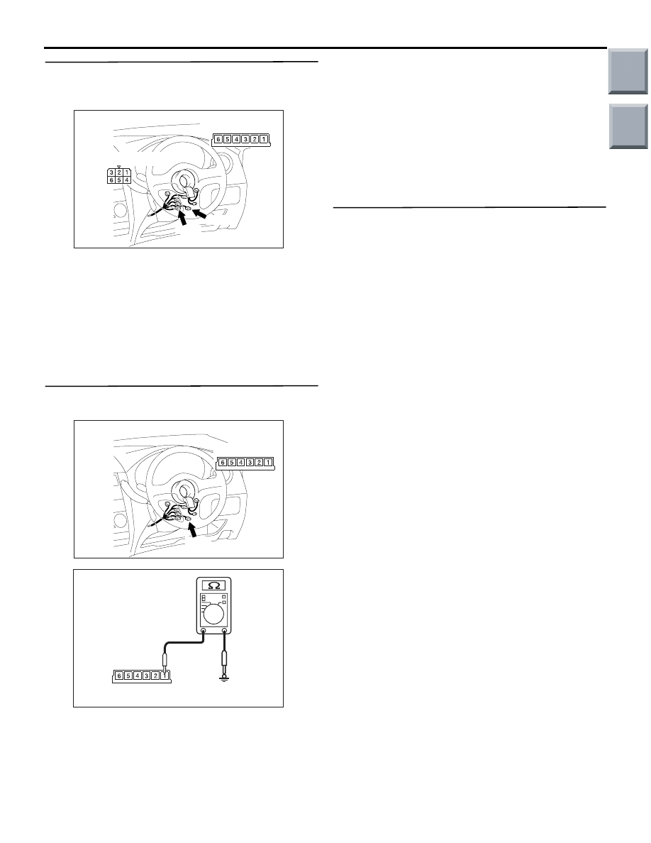
STEP 4. Measure the resistance at B-142 steering
wheel sensor connector.
(1) Disconnect B-142 steering wheel sensor
connector, and measure at the wiring
harness-side connector.
(2) Measure the resistance between B-142 steering
wheel sensor connector terminal No. 1 and the
body earth.
OK: Continuity exists (2
Ω or less)
Q: Is the check result normal?
YES :
Go to Step 5.
NO :
Repair the wiring harness between B-142
steering wheel sensor connector terminal
No. 1 and the body earth.
STEP 5. Retest the system.
Check that the steering wheel sensor communicates
with the ASC-ECU normally.
NOTE: When the steering wheel sensor related diag-
nosis code is not set to ACS-ECU and the steering
wheel sensor is normal at the M.U.T.-III CAN bus
diagnosis, the communication with the steering
wheel sensor is normal.
Q: Is the check result normal?
YES :
Intermittent malfunction (Refer to GROUP
00
− How to Cope with Intermittent
.)
NO :
Replace the steering wheel sensor.
AC601114
Connectors: B-141, B-142
AC
B-141
B-141: Harness side
B-142
B-142: Harness side
AC601114
Connector: B-142
AB
B-142
Harness side
AC601118AB
B-142: Harness side
Main
Index
Group
TOC
Нет комментариевНе стесняйтесь поделиться с нами вашим ценным мнением.
Текст