Mitsubishi Colt Ralliart. Manual — part 217
AC403232AB
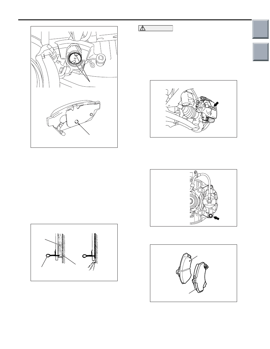
Stopper groove
Protrusion
ON-VEHICLE SERVICE
BASIC BRAKE SYSTEM
35A-14
8. Set as shown so that the protrusion on the pad
assembly rear face is engaged in the piston
stopper groove.
9. Install the pad and caliper assembly, and check
the brake drag force (Refer to
).
DISC BRAKE PAD CHECK AND
REPLACEMENT <RALLIART
VERSION-R>
M1351002300859
<FRONT>
NOTE:
AC000879
When new
When worn
AD
Pad
Wear indicator
Brake
disc
The brake pads have indicators that contact the
brake disc when the brake pad thickness becomes
1.5 mm, and emit a squealing sound to warn the
driver.
CAUTION
• Whenever a pad must be replaced, replace
both LH and RH wheel pads as a set to pre-
vent the vehicle from pulling to one side when
braking.
• If there is a significant difference in the thick-
ness of the pads on the left and right sides,
check the sliding condition of the piston and
slide pins.
AC601033AC
1. Check the brake pad thickness through the caliper
body check port.
Standard value: 10.5 mm
Minimum limit: 1.5 mm
AC601051AC
2. Remove the bolt. Pivot the caliper assembly and
hold it with wires.
AC601035AC
1
2
3. Remove the following parts from caliper
assembly.
(1) Pad assembly <RH> or Pad and wear
indicator assembly <LH>
(2) Pad assembly
Main
Index
Group
TOC

ON-VEHICLE SERVICE
BASIC BRAKE SYSTEM
35A-15
4. In order to measure the brake drag force after pad
installation, measure the rotary-sliding resistance
of the hub with the pads removed <Refer to
5. Install the pads and caliper assembly, and then
check the brake drag force <Refer to
>.
<Rear>
AC601034AD
1. Visually check the thickness of brake pad from the
inspection hole of the caliper body.
Standard value: 10.0 mm
Limit value: 1.5 mm
2. When the thickness is lower than the limit value,
replace the both brake pads (right and left) as a
set.
3. Disengage the connection between the rear brake
caliper and rear parking brake cable.
AC601034AE
4. Remove the bolt, and swivel the caliper assembly
upward to retain with a wire or other similar
material.
AC601036AC
1
2
5. Remove the following parts from the caliper
assembly.
(1) Pad assembly <RH> or Pad and wear
indicator assembly <LH>
(2) Pad assembly
6. In order to measure the brake drag force after pad
installation, measure the hub sliding torque with
no pad attached (Refer to
CAUTION
Keep grease or other fouling off the pad and
brake disc friction surface.
AC402607AD
MB996049
7. Clean the piston, and press the piston into the
cylinder using the special tool, rear disc brake
piston driver (MB996049).
8. Install the pad and caliper assembly, and check
the brake drag force (Refer to
Main
Index
Group
TOC

ON-VEHICLE SERVICE
BASIC BRAKE SYSTEM
35A-16
DISC BRAKE ROTOR CHECK
M1351002900594
CAUTION
Disc brakes must be kept within the allowable
service values in order to maintain normal brake
operation.
Before turning the brake disc, the following condi-
tions should be checked.
Inspection item
Remark
Scratches, rust, saturated lining materials and wear
• If the vehicle is not driven for a long period of
time, sections of the discs that are not in contact
with the pads will become rusty, causing noise
and shuddering.
• If grooves and scratches resulting from excessive
disc wear are not removed prior to installing a new
pad assembly, there will be inadequate contact
between the disc and the lining (pad) until the
pads conform to the disc.
Run-out
Excessive run-out of the discs will increase the pedal
depression resistance due to piston kick-back.
Change in thickness (parallelism)
If the thickness of the disc changes, this will cause
pedal pulsation, shuddering and surging.
Inset or warping (flatness)
Overheating and improper handling while servicing
will cause warping or distortion.
BRAKE DISC THICKNESS CHECK
ACX00668
1. Using a micrometer, measure disc thickness at
eight positions, approximately 45 degrees apart
and 10 mm in from the outer edge of the disc.
Standard value:
<Front (LS, VR)> 20.0 mm
<Front (VR-X)> 24.0 mm
<Front (RALLIART Version-R)> 25.8 mm
<Rear> 10.0 mm
Limit value:
<Front (LS, VR)> 18.4 mm
<Front (VR-X)> 22.4 mm
<Front (RALLIART Version-R)> 23.5 mm
<Rear (VR-X)> 8.4 mm
<Rear (RALLIART Version-R)> 8.0 mm
NOTE: Thickness variation (at least 8 positions)
should not be more than 0.015 mm.
Main
Index
Group
TOC
ON-VEHICLE SERVICE
BASIC BRAKE SYSTEM
35A-17
CAUTION
• After a new brake disc is installed, always
grind the brake disc with on-the-car type
brake lathe. If this step is not carried out, the
brake disc run-out exceeds the specified
value, resulting in judder.
•
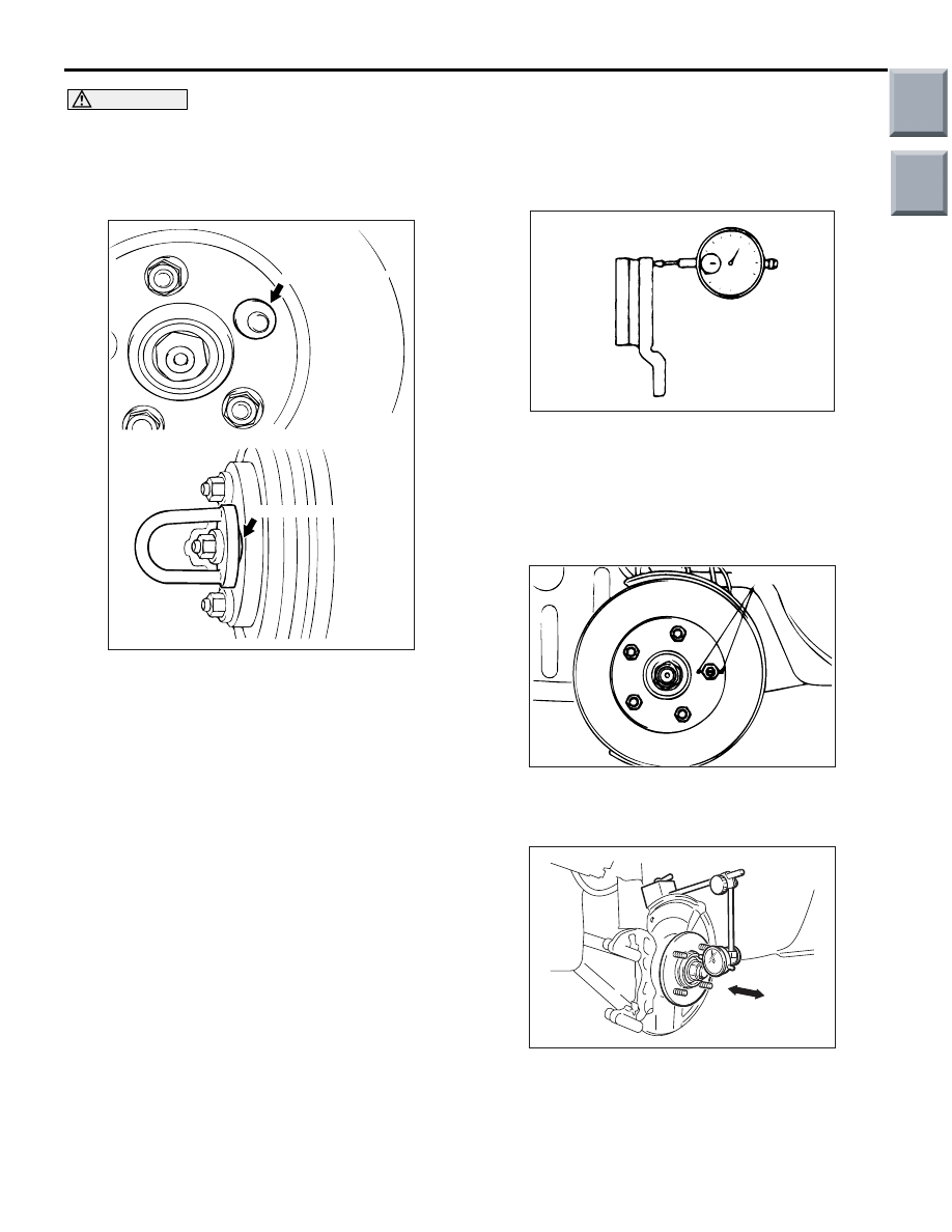
AC006226AD
M12 Flat washer
M12 Flat washer
When the on-the-car type lathe is used, first
install M12 flat washer on the stud bolt in the
brake disc side according to the figure, and
then install the adapter. If the adapter is
installed with M12 flat washer not seated, the
brake disc rotor may be deformed, resulting
in inaccurate grinding.
• Grind the brake disc with all wheel nuts diag-
onally and equally tightened to the specified
torque 100 N
⋅m. When all numbers of wheel
nuts are not used, or the tightening torque is
excessive or not equal, the brake disc rotor or
drum may be deformed, resulting in judder.
2. If the disc thickness is less than the limits, replace
it with a new one.
If thickness variation exceeds the specification,
turn rotor with an on-the-car type brake lathe
("MAD, DL-8700PF" or equivalent). If the
calculated final thickness after turning the rotor is
less than the standard value, replace the disc.
FRONT BRAKE DISC RUN-OUT CHECK
AND CORRECTION
1. Remove the brake assembly, and then hold it with
wire.
2. Temporarily install the disc with the hub nut.
ACX00669
3. Place a dial gauge approximately 5 mm from the
outer circumference of the brake disc, and
measure the run-out of the disc.
Limit: 0.06 mm
4. If the brake disc run-out exceeds the limit, correct
it as follows:
AC201323AC
Chalk marks
(1) Chalk phase marks on the wheel stud and the
brake disc, which run-out is excessive as
shown.
AC314229AB
(2) Remove the brake disc. Then place a dial
gauge as shown, and measure the axial play
by pushing and pulling the wheel hub.
Limit: 0.05 mm
Main
Index
Group
TOC
Нет комментариевНе стесняйтесь поделиться с нами вашим ценным мнением.
Текст