Mitsubishi Colt Ralliart. Manual — part 244
TROUBLESHOOTING
ANTI-SKID BRAKING SYSTEM (ABS)
35B-68
COMMENTS ON TROUBLE SYMPTOM
• If the ABS system fails, the ABS-ECU will send a
lamp drive signal to the combination meter
through the CAN communication lines.
• If the combination meter detects a ABS time-out
due to a failure in the power supply to the
ABS-ECU or abnormal CAN communication, the
combination meter illuminates the lamp.
• If the CAN bus communication fails, refer to
GROUP 54D, CAN Bus Diagnostics Table
• If a trouble occurs in the power supply to the
ABS-ECU (i.e. excessively high resistance in the
power supply or earth lines), this trouble symp-
tom will appear., but the diagnosis code will not
be set. Then, if you drive the vehicle at 6 km/h or
more, the ECU will set diagnosis code C1861.
• Perform the actuator test to extinguish the lamp
in the combination meter. If it does not extinguish,
replace the combination meter. If it extinguishes,
replace the ABS-ECU.
• It is also suspected that the combination meter
does not obey the commands from the
ABS-ECU. If the combination meter does not
function after the ABS-ECU is replaced, replace
the combination meter.
POSSIBLE CAUSES
• Damaged harness wires and connectors
• Defective combination meter (incorporating the
meter-ECU)
• The ABS-ECU is defective.
• The power supply circuit is defective.
DIAGNOSIS PROCEDURE
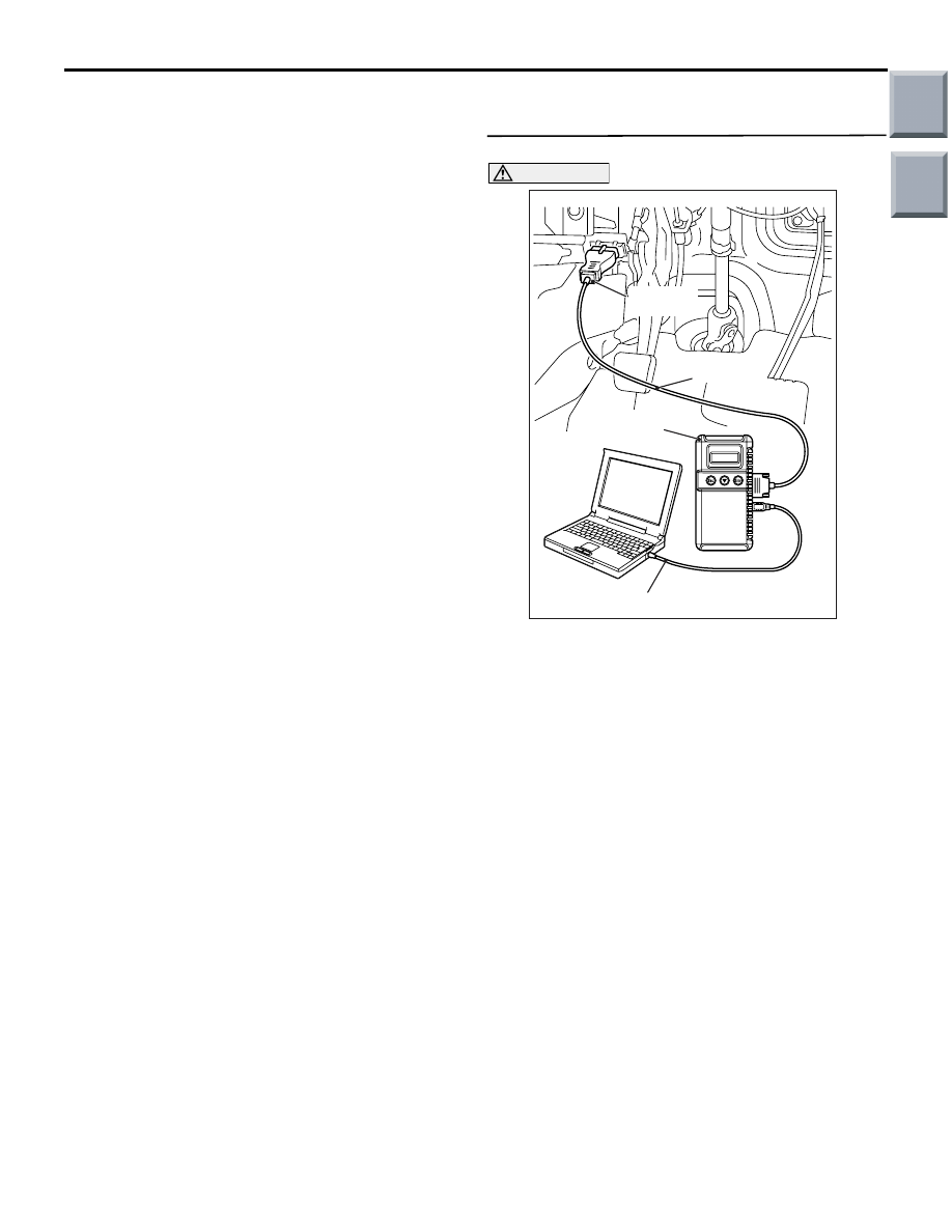
STEP 1. M.U.T.-III CAN bus diagnostics
CAUTION
Before connecting or disconnecting the
M.U.T.-III, turn the ignition switch to the "LOCK"
(OFF) position.
(1) Connect M.U.T.-III to the 16-pin diagnosis
connector.
(2) Turn the ignition switch to the "ON" position.
(3) Diagnose the CAN bus line.
(4) Turn the ignition switch to the "LOCK" (OFF)
position.
Q: Is the check result normal?
YES :
Go to Step 2.
NO :
Repair the CAN bus line (Refer to GROUP
54D, Diagnosis
AC206895
AC
Diagnosis
connector
MB991827
MB991824
MB991910
Main
Index
Group
TOC
TROUBLESHOOTING
ANTI-SKID BRAKING SYSTEM (ABS)
35B-69
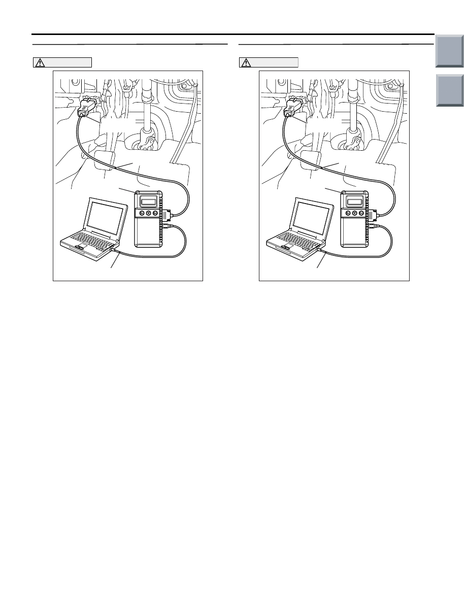
STEP 2. M.U.T.-III diagnosis code
CAUTION
Before connecting or disconnecting the
M.U.T.-III, turn the ignition switch to the "LOCK"
(OFF) position.
(1) Connect M.U.T.-III to the 16-pin diagnosis
connector.
(2) Turn the ignition switch to the "ON" position.
(3) Check whether the ABS-related diagnosis code is
set.
(4) Turn the ignition switch to the "LOCK" (OFF)
position.
Q: Is the check result normal?
YES :
Go to Step 3.
NO :
Carry out the diagnosis for the diagnosis
code (Refer to
).
STEP 3. M.U.T.-III diagnosis code
CAUTION
Before connecting or disconnecting the
M.U.T.-III, turn the ignition switch to the "LOCK"
(OFF) position.
(1) Connect M.U.T.-III to the 16-pin diagnosis
connector.
(2) Turn the ignition switch to the "ON" position.
(3) Drive the vehicle at 10 km/h or more. Then use
the M.U.T.-III to check whether the ABS
diagnosis code is reset.
(4) Turn the ignition switch to the "LOCK" (OFF)
position.
Q: Is the check result normal?
YES :
Go to Step 4.
NO :
Carry out the diagnosis for the diagnosis
code (Refer to
).
AC206895
AC
Diagnosis
connector
MB991827
MB991824
MB991910
AC206895
AC
Diagnosis
connector
MB991827
MB991824
MB991910
Main
Index
Group
TOC
TROUBLESHOOTING
ANTI-SKID BRAKING SYSTEM (ABS)
35B-70
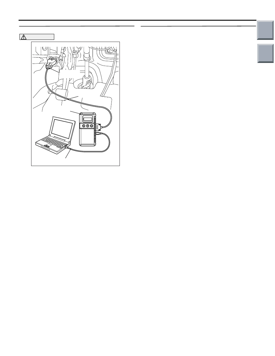
STEP 4. M.U.T.-III actuator test
CAUTION
Before connecting or disconnecting the
M.U.T.-III, turn the ignition switch to the "LOCK"
(OFF) position.
(1) Connect M.U.T.-III to the 16-pin diagnosis
connector.
(2) Turn the ignition switch to the "ON" position.
(3) Execute combination meter actuator test.
• Item A1: Indicator lamp and warning lamp
(extinguish)
(4) Turn the ignition switch to the "LOCK" (OFF)
position.
(5) Disconnect M.U.T.-III.
Q: Does the ABS warning lamp extinguish normally?
YES : .
Replace the combination meter (integrated
with meter-ECU) (Refer to GROUP 54A,
Combination Meter
). Then go to
Step 5.
NO : .
Replace the hydraulic unit (integrated with
ABS-ECU) (Refer to
).
STEP 5. Recheck the trouble symptom.
Q: Does the ABS warning lamp extinguish after the
engine has been started?
YES :
This diagnosis is complete.
NO :
Replace the combination meter (integrated
with meter-ECU) (Refer to GROUP 54A,
Combination Meter
).
AC206895
AC
Diagnosis
connector
MB991827
MB991824
MB991910
Main
Index
Group
TOC

TROUBLESHOOTING
ANTI-SKID BRAKING SYSTEM (ABS)
35B-71
Inspection Procedure 5: The ABS operates too frequently (no diagnosis code is set)
COMMENTS ON TROUBLE SYMPTOM
• This trouble symptom will not appear due to a
failure in wiring harness (open or short circuit, or
excessive resistance). Therefore, if the sensors
are installed properly and the check result does
not indicate any problems, replace the ABS-ECU.
POSSIBLE CAUSES
• Wheel speed sensor malfunction
• Hub malfunction
• ABS-ECU malfunction
DIAGNOSIS PROCEDURE
STEP 1. Check the wheel speed sensors for
proper installation.
Check that the wheel speed sensors are installed
correctly (e.g. loosely tightened bolts).
Q: Is the check result normal?
YES :
Go to Step 2.
NO :
Reinstall the wheel speed sensor(s)
properly.
STEP 2. Remove the wheel speed sensors and
check them.
Refer to
Q: Is the check result normal?
YES :
Go to Step 3.
NO :
Replace the wheel speed sensor (Refer to
).
STEP 3. Check the encoder for detecting wheel
speed.
Check the encoder for presence of foreign objects or
deformation.
Q: Is the check result normal?
YES :
Go to Step 4.
NO :
If foreign objects are found, clean the
encoder. If deformation is found, replace the
hub [Refer to GROUP 26, Front Axle Hub
Assembly
<Front (vehicles with 14
15 inch brake)> or GROUP 27, Rear Axle
Hub
STEP 4. Check the wheel bearing for excessive
play.
Front: refer to GROUP 26, On-vehicle Service
−
Wheel Bearing Axial Play Check
.
Rear: refer to GROUP 27, On-vehicle Service
−
Wheel Bearing Axial Play Check
.
Q: Is the check result normal?
YES :
Go to Step 5.
NO :
Replace the hub assembly [Refer to
GROUP 26, Front Axle Hub Assembly
<Front (vehicles with 14 inch brake)>
or
<Front (vehicles with 15 inch
brake)> or GROUP 27, Rear Axle Hub
<Rear>].
STEP 5. Recheck the trouble symptom.
Q: Does the ABS operate too frequently?
YES :
The malfunction is intermittent. Refer to
GROUP 00, How to Use
Troubleshooting/Inspection Service Points
−
How to Cope with Intermittent Malfunction
.
NO :
Replace the hydraulic unit (integrated with
ABS-ECU) (Refer to
).
Main
Index
Group
TOC
Нет комментариевНе стесняйтесь поделиться с нами вашим ценным мнением.
Текст