Mitsubishi Colt Ralliart. Manual — part 404
SYMPTOM PROCEDURES
SMART WIRING SYSTEM (SWS) USING SWS MONITOR
54C-124
Step 5. Check the door mirror assemblies.
Check whether the door mirror assemblies work nor-
mally (Refer to GROUP 51
− Door Mirror
Q: Is the check result normal?
YES :
Go to Step 6.
NO :
Replace the door mirror assemblies.
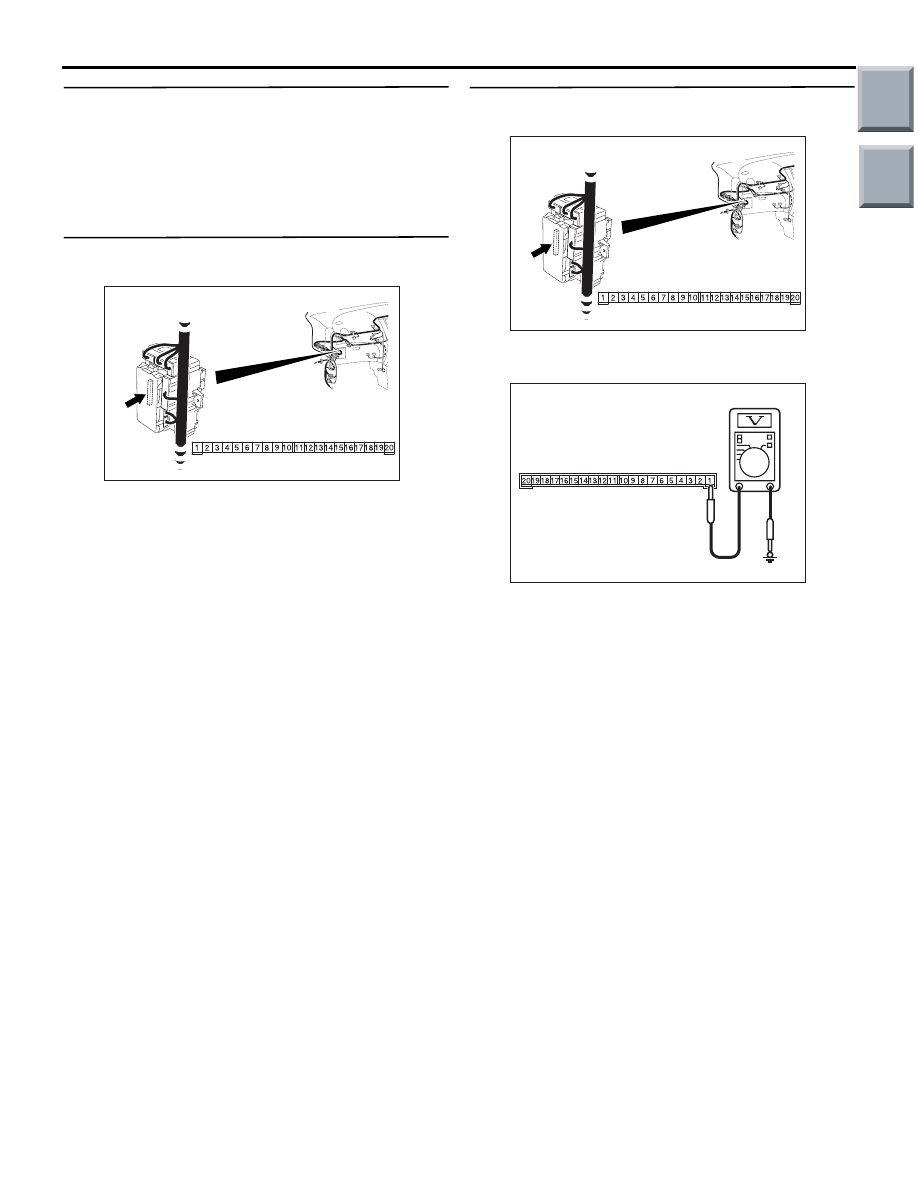
Step 6. Connector check: B-134 ETACS-ECU
connector
Q: Is the check result normal?
YES :
Go to Step 7.
NO :
Repair the connector.
Step 7. Voltage measurement at the B-134
ETACS-ECU connector
(1) Remove the ETACS-ECU, and measure at the
junction block side.
(2) Check the voltage between the B-134
ETACS-ECU connector terminal No.1 and body
earth.
OK: System voltage
Q: Is the check result normal?
YES :
Go to Step 9.
NO :
Go to Step 8.
AC313872 AH
Connector: B-134
Harness side
Junction block (Rear view)
AC313872 AH
Connector: B-134
Harness side
Junction block (Rear view)
AC313972
Connector B-134
(Harness side)
AR
Main
Index
Group
TOC

SYMPTOM PROCEDURES
SMART WIRING SYSTEM (SWS) USING SWS MONITOR
54C-125
Step 8. Check the wiring harness between B-134
ETACS-ECU connector terminal No.20 to the
fusible link (1)
NOTE:
Prior to the wiring harness inspection, check junction
block connector B-108, and repair if necessary.
• Check the power supply line to the battery for
open circuit.
Q: Is the check result normal?
YES :
The trouble can be an intermittent
malfunction (Refer to GROUP 00
− How to
use Troubleshooting/inspection Service
Points
− How to Cope with Intermittent
).
NO :
Repair the wiring harness.
Step 9. Retest the system
Check that the electric retractable remote controlled
mirror works normally.
Q: Is the check result normal?
YES :
The trouble can be an intermittent
malfunction (Refer to GROUP 00
− How to
use Troubleshooting/inspection Service
Points
− How to Cope with Intermittent
).
NO :
Replace the ETACS-ECU.
AC313872 AH
Connector: B-134
Harness side
Junction block (Rear view)
AC313870
Connector: B-108
BD
Junction block (Front view)
B-108(B)
Harness side
Main
Index
Group
TOC

SYMPTOM PROCEDURES
SMART WIRING SYSTEM (SWS) USING SWS MONITOR
54C-126
INSPECTION PROCEDURE H-2: Electric retractable remote controlled door mirror timer function does
not at all.
CAUTION
Whenever the ECU is replaced, ensure that the
input and output signal circuits are normal.
COMMENTS ON TROUBLE SYMPTOM
If the door mirror can be folded and unfolded with the
remote controlled mirror switch (fold/unfold switch),
the ETACS-ECU may be defective.
POSSIBLE CAUSES
• Malfunction of the ETACS-ECU
DIAGNOSTIC PROCEDURE
Step 1. Check the electric retractable door
mirrors operation.
Check that the door mirror is folded and unfolded
with the remote controlled mirror switch when the
ignition switch is at ACC position.
• Ignition switch: ACC
Q: Is the check result normal?
YES :
Go to Step 2.
NO :
Refer to inspection procedure H-1 "Electric
retractable remote controlled door mirror
does not work at all
Step 2. ECU check on the SWS monitor
Check that the power supply and earth lines to the
ETACS-ECU and the SWS communication lines are
normal.
• Ignition switch: OFF
ECU TO BE CHECKED
• ETACS ECU
OK: "OK" is displayed on the "ETACS ECU"
menu.
Q: Is the check result normal?
YES :
Go to Step 3.
NO :
Refer to Inspection Procedure A-3
"Communication with ETACS-ECU is not
possible
."
Step 3. SWS monitor data list.
Check the SWS communication signal, which are
related to the electric retractable door mirror timer
function.
<Selected item> ETACS ECU
• Ignition switch: IG1
OK: Normal condition is displayed.
Q: Is the check result normal?
YES :
Go to Step 4.
NO :
Refer to inspection procedure N-2 "The
ignition switch (IG1) signal is not received
."
Step 4. Retest the system.
Check that the electric retractable door mirror timer
function works normally.
Q: Is the check result normal?
YES :
The trouble can be an intermittent
malfunction (Refer to GROUP 00
− How to
use Troubleshooting/inspection Service
Points
− How to Cope with Intermittent
).
NO :
Replace the ETACS-ECU.
Item No.
Item name
Normal
condition
Item 30
IG SW IG1
ON
Main
Index
Group
TOC

SYMPTOM PROCEDURES
SMART WIRING SYSTEM (SWS) USING SWS MONITOR
54C-127
INSPECTION PROCEDURE H-3: Vehicle speed-dependent unfolding function does not work normally.
CAUTION
Whenever the ECU is replaced, ensure that the
input and output signal circuits are normal.
COMMENTS ON TROUBLE SYMPTOM
If this function does not work normally, the input sig-
nal circuit(s) below or the ETACS-ECU may be
defective.
POSSIBLE CAUSES
• Defective vehicle speed signal
(engine-CVT-ECU)
• Malfunction of the ETACS-ECU
• Damaged harness wires and connectors
DIAGNOSIS PROCEDURE
Step 1. M.U.T.-III CAN bus diagnostics
Use the M.U.T.-III to diagnose the CAN bus lines.
Q: Is the check result normal?
YES :
Go to Step 2.
NO :
Repair the CAN bus line (Refer to GROUP
54D
− Diagnosis
Step 2. M.U.T.-III other system diagnosis code
Check whether the combination meter-related diag-
nosis code is set.
Q: Is the check result normal?
YES :
Diagnose the combination meter (Refer to
GROUP 54A
− Troubleshooting
NO :
Go to Step 3.
Step 3. Retest the system.
Check that the vehicle speed-dependent unfolding
function of the door mirrors works normally.
Q: Is the check result normal?
YES :
The trouble can be an intermittent
malfunction (Refer to GROUP 00
− How to
use Troubleshooting/inspection Service
Points
− How to Cope with Intermittent
).
NO :
Replace the ETACS-ECU.
INSPECTION PROCEDURE H-4: Keyless entry system-linked fold/unfold function does not work
normally.
CAUTION
Whenever the ECU is replaced, ensure that the
input and output signal circuits are normal.
COMMENTS ON TROUBLE SYMPTOM
If this function does not work normally, keyless entry
transmitter input signal circuit or the ETACS-ECU
may be defective.
POSSIBLE CAUSES
• Defective keyless entry transmitter
• Malfunction of the ETACS-ECU
• Damaged harness wires and connectors
DIAGNOSIS PROCEDURE
Step 1. Check the keyless entry operation.
Check that the keyless entry system works normally.
Q: Is the check result normal?
YES :
Go to Step 2.
NO :
Refer to inspection procedure E-1 "Keyless
entry system does not work
."
Step 2. Retest the system.
Check that the keyless entry interlock fold/unfold
function for the door mirrors works normally.
Q: Is the check result normal?
YES :
The trouble can be an intermittent
malfunction (Refer to GROUP 00
− How to
use Troubleshooting/inspection Service
Points
− How to Cope with Intermittent
).
NO :
Replace the ETACS-ECU.
Main
Index
Group
TOC
Нет комментариевНе стесняйтесь поделиться с нами вашим ценным мнением.
Текст