Mitsubishi Colt Ralliart. Manual — part 526

TROUBLESHOOTING
HEATER, AIR CONDITIONER AND VENTILATION
55A-12
Step 2. M.U.T.-III diagnosis code
Check whether the air conditioner sets a diagnosis
code or not.
Q: Is the check result normal?
YES :
Go to Step 3.
NO :
Refer to diagnosis code chart
Step 3. M.U.T.-III data list
Check that the following service data display con-
tents are normal. (Refer to
.)
• Item 04: Pressure sensor
Q: Is the check result normal?
YES :
Go to Step 4.
NO :
Inspection Procedure 10: Refer to A/C
pressure sensor system
Step 4. Connector check: A-130 A/C compressor
connector and A-08 engine-CVT-ECU
AC313811
Connector: A-08
AL
Harness side
A-08 (B)
AC313797
Connector: A-130
AB
Harness side
A-130 (B)
Q: Is the check result normal?
YES :
Go to Step 5.
NO :
Repair the connector.
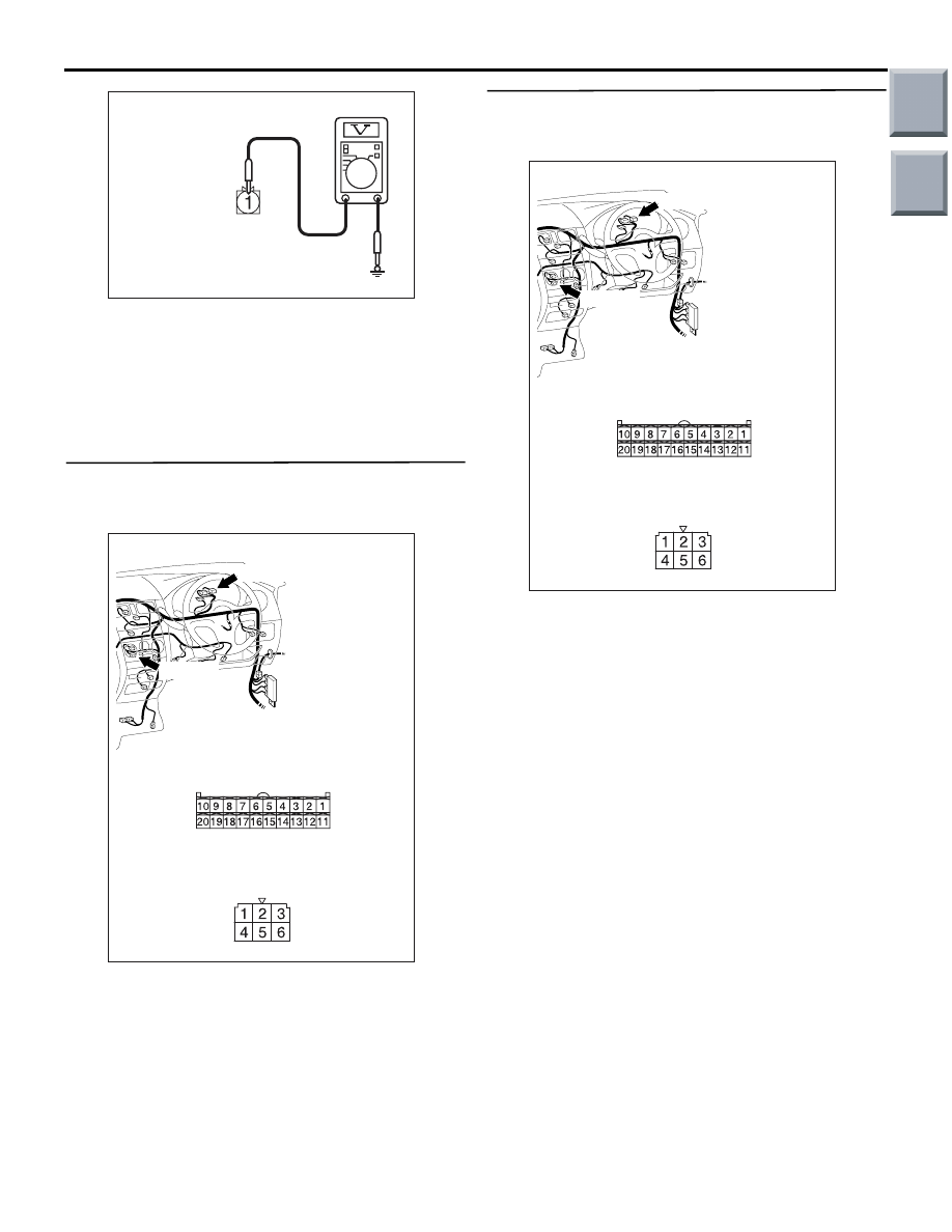
Step 5. Voltage measurement at A-130 A/C
compressor connector.
AC313797
Connector: A-130
AB
Harness side
A-130 (B)
(1) Disconnect the connector, and measure at the
wiring harness side.
AC313811
Connector: A-08
AL
Harness side
A-08 (B)
AC309471
AC309471
Connector A-08
(Harness side)
AL
(2) Disconnect engine-CVT-ECU connector A-08
and earth terminal 6.
Main
Index
Group
TOC
AC310507
Connector A-130
(Harness side)
EY
TROUBLESHOOTING
HEATER, AIR CONDITIONER AND VENTILATION
55A-13
(3) Voltage between terminal 1 and body earth.
OK: System voltage
Q: Is the check result normal?
YES :
Go to Step 6.
NO :
Refer to Inspection Procedure 7 " The
compressor does not work
".
Step 6. Connector check: B-31 blower switch
connector and B-15 combination meter
connector
AC401056
AF
Connectors: B-15, B-31
Harness side
B-15 (B)
B-31 (B)
B-15
Harness side
B-31
Q: Is the check result normal?
YES :
Go to Step 7.
NO :
Repair the connector.
Step 7. Check the wiring harness between B-31
blower switch connector terminal No.1 and B-15
combination meter connector terminal No.7.
AC401056
AF
Connectors: B-15, B-31
Harness side
B-15 (B)
B-31 (B)
B-15
Harness side
B-31
• Check the blower switch signal line and earth line
for open or short circuit.
Q: Is the check result normal?
YES :
Go to Step 8.
NO :
Repair the wiring harness.
Main
Index
Group
TOC
TROUBLESHOOTING
HEATER, AIR CONDITIONER AND VENTILATION
55A-14
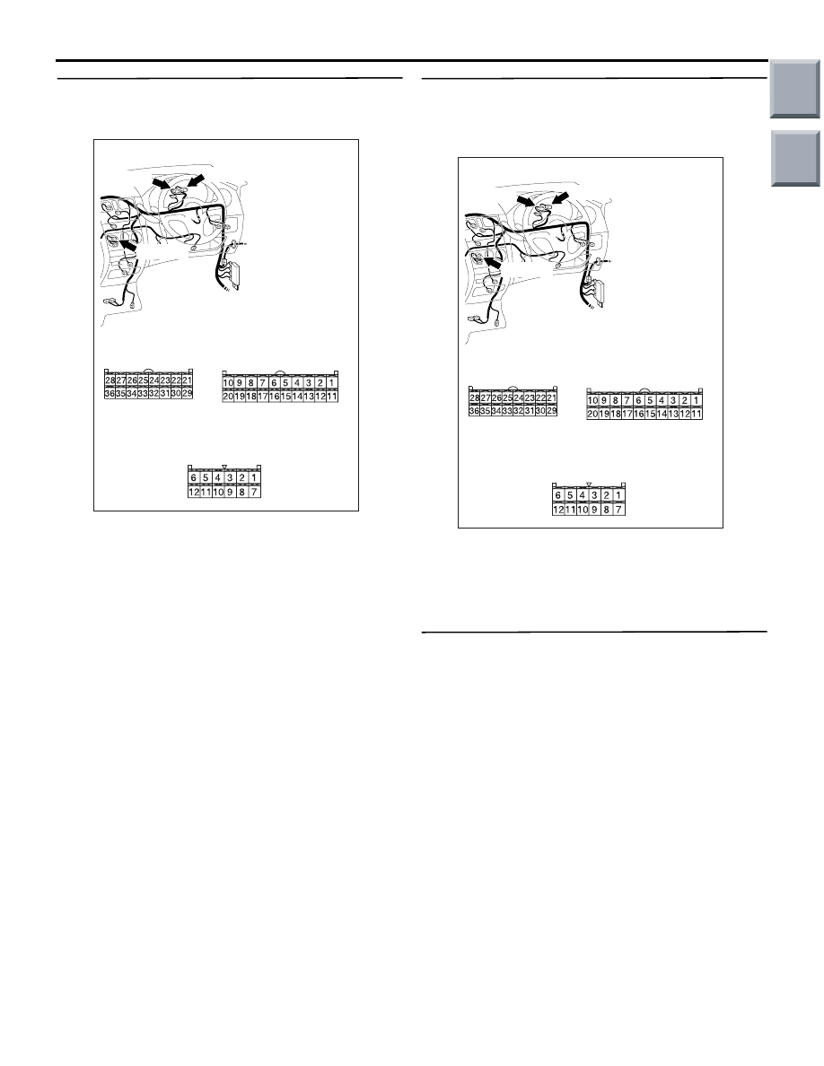
Step 8. Connector check: B-30 heater control
assembly connector, B-14 and B-15 combination
meter connector
AC401056
AG
Connectors: B-14, B-15, B-30
Harness side
B-15 (B)
B-30 (B)
B-15
Harness side
B-30
B-14 (B)
Harness side
B-14
Q: Is the check result normal?
YES :
Go to Step 9.
NO :
Repair the connector.
Step 9. Check the wiring harness between B-14,
B-15 combination meter connector (terminals 29,
35 and 6) and B-30 heater control assembly
connector (terminals 6, 7 and 10).
AC401056
AG
Connectors: B-14, B-15, B-30
Harness side
B-15 (B)
B-30 (B)
B-15
Harness side
B-30
B-14 (B)
Harness side
B-14
• Check the input line for open or short circuit.
Q: Is the check result normal?
YES :
Go to Step 10.
NO :
Repair the wiring harness.
Step 10. Refrigerant level check
Check that the refrigerant level is adequate. Refer to
Q: Is the check result normal?
YES :
Intermittent malfunction. (Refer to GROUP
00, How to Cope with Intermittent
Malfunction
.)
NO :
Charge or remove the refrigerant level.
Refer to
.
Main
Index
Group
TOC

TROUBLESHOOTING
HEATER, AIR CONDITIONER AND VENTILATION
55A-15
Inspection Procedure 4: The blower does not work
Blower Motor Circuit
BLOWER
SWITCH
RESISTOR
BLOWER
MOTOR
FUSIBLE
LINK
6
Wire colour code
B : Black LG : Light green G : Green L : Blue W : White Y : Yellow SB : Sky blue
BR : Brown O : Orange GR : Gray R : Red P : Pink V : Violet
IGNITION
SWITCH (IG2)
BLOWER
RELAY
COMMENTS ON TROUBLE SYMPTOM
If the blower motor does not operate, the blower
motor circuit system may be defective.
POSSIBLE CAUSES
• Malfunction of the front blower relay
• Malfunction of the blower motor
• Malfunction of the blower switch
• Damaged the wiring harness or connectors
Main
Index
Group
TOC
Нет комментариевНе стесняйтесь поделиться с нами вашим ценным мнением.
Текст