Mitsubishi Colt Ralliart. Manual — part 462

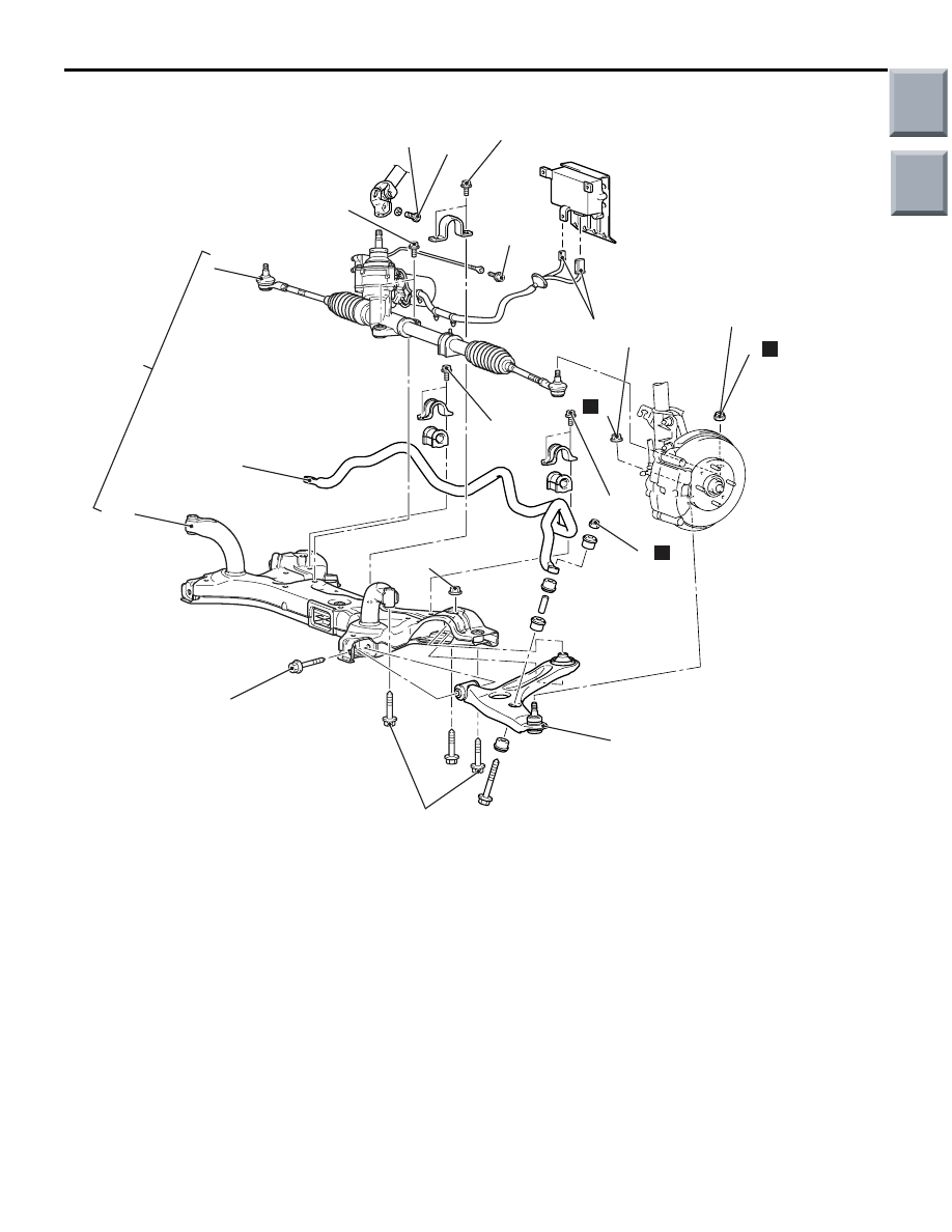
FRONT AXLE CROSSMEMBER
POWER PLANT MOUNT
32-13
<M/T>
AC601314AB
18 ± 2 N·m
4
5
6
10
58 ± 6 N·m
30 ± 5 N·m
58 ± 6 N·m
25 ± 5 N·m
66 ± 6 N·m
123 ± 12 N·m*
1
N
3
N
9.0 ± 2.0 N·m
30 ± 5 N·m
123 ± 12 N·m
58 ± 6 N·m
9
8
7
2
N
123 ± 12 N·m
Removal steps
<<
A
>>
1.
Tie rod end and knuckle connection
>>
F
2.
Self-locking nut
<<
A
>>
3.
Lower arm and knuckle connection
4.
Lower arm assembly
<<
B
>>
>>
E
5.
Steering gear and steering column
assembly connecting bolt
>>
D
6.
Electric power steering-ECU
connector
<<
C
>>
>>
C
7.
Front axle No.1 crossmember
assembly
>>
B
8.
Steering gear and linkage assembly
>>
A
9.
Stabilizer bar
10. Front axle No.1 crossmember
Removal steps (Continued)
Main
Index
Group
TOC
FRONT AXLE CROSSMEMBER
POWER PLANT MOUNT
32-14
<CVT>
AC405878 AC
18 ± 2 N·m
4
5
6
10
80 ± 10 N·m
50 ± 10 N·m
25 ± 5 N·m
66 ± 6 N·m
123 ± 12 N·m*
1
N
3
N
9.0 ± 2.0 N·m
50 ± 10 N·m
123 ± 12 N·m
9
8
7
2
N
123 ± 12 N·m
80 ± 10 N·m
Removal steps
<<
A
>>
1.
Tie rod end and knuckle connection
>>
F
2.
Self-locking nut
<<
A
>>
3.
Lower arm and knuckle connection
4.
Lower arm assembly
<<
B
>>
>>
E
5.
Steering gear and steering column
assembly connecting bolt
>>
D
6.
Electric power steering-ECU
connector
<<
C
>>
>>
C
7.
Front axle No.1 crossmember
assembly
>>
B
8.
Steering gear and linkage assembly
>>
A
9.
Stabilizer bar
10. Front axle No.1 crossmember
Removal steps (Continued)
Main
Index
Group
TOC

FRONT AXLE CROSSMEMBER
POWER PLANT MOUNT
32-15
REMOVAL SERVICE POINTS
<<A>> TIE ROD END AND
KNUCKLE/LOWER ARM AND KNUCKLE
DISCONNECTION
CAUTION
• Do not remove the nut from ball joint. Loosen
it and use the special tool to avoid possible
damage to ball joint threads.
•
AC208247AJ
Cord
Bolt
MB991897
or
MB992011
Nut
Ball joint
Hang the special tool with cord to prevent it
from falling.
1. Install the special tool ball joint remover
(MB991897 or MB992011) as shown in the figure.
AC104739AB
Parallel
Knob
Bolt
Correct
Wrong
2. Turn the bolt and knob as necessary to make the
jaws of the special tool parallel, tighten the bolt by
hand and confirm that the jaws are still parallel.
NOTE: When adjusting the jaws in parallel, make
sure the knob is in the position shown in the fig-
ure.
3. Disengage the lower arm and tie rod end from the
knuckle by tightening the bolt with a wrench.
<<B>> STEERING GEAR AND STEERING
COLUMN ASSEMBLY DISCONNECTION
AC207740 AB
Clip
Steering column
bolt
Claw
Shaft B
Shaft A
1. Remove the steering column bolt connecting
steering gear to steering column assembly.
2. Disconnect the steering gear from the steering
column assembly while sliding shaft A to shaft B
with the clip claw as shown is pinched.
<<C>> FRONT AXLE NO.1
CROSSMEMBER ASSEMBLY REMOVAL
AC402971AC
Piece of wood
Transmission
jack
Use a transmission jack to hold the front axle No.1
crossmember, and then remove the crossmember
mounting nuts and bolts.
Main
Index
Group
TOC
FRONT AXLE CROSSMEMBER
POWER PLANT MOUNT
32-16
INSTALLATION SERVICE POINTS
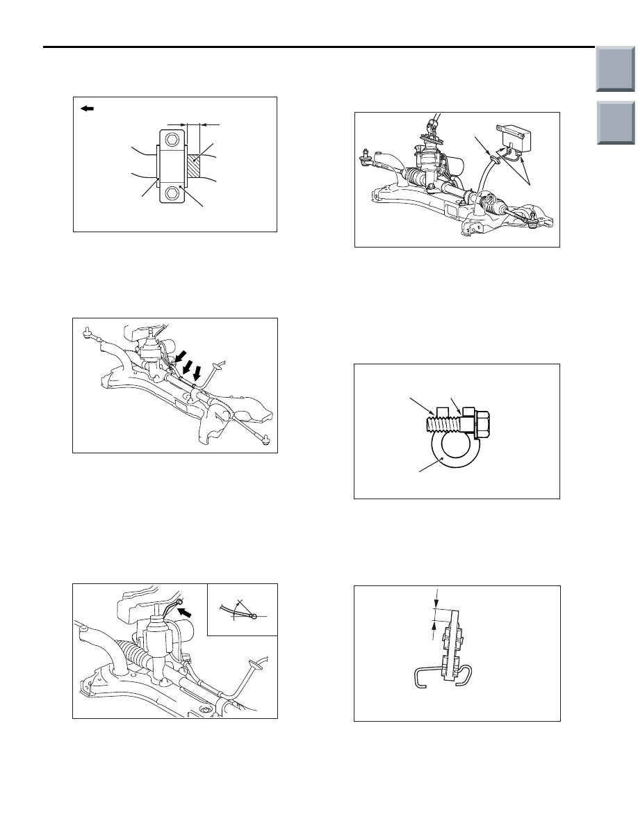
>>A<< STABILIZER BAR INSTALLATION
AC405476 AB
Stabilizer bar
bracket (LH)
Outside of
vehicle
Stabilizer
bushing (LH)
Approximately
10 mm
Identification
mark
Align the stabilizer bar identification mark with the
right end of the stabilizer bushing (LH).
>>B<< STEERING GEAR AND LINKAGE
ASSEMBLY INSTALLATION
AC403472AC
Harness clip
After installing the steering gear and linkage assem-
bly to the front axle No.1 crossmember, secure the 3
harness clips of the steering gear and linkage
assembly to the front axle No.1 crossmember.
>>C<< FRONT AXLE NO.1
CROSSMEMBER ASSEMBLY
INSTALLATION
AC403448AB
View A
A
0 to 45˚
After installing the front axle No.1 crossmember
assembly, tighten the bolt to the specified torque so
that the installation angle of the earth cable is within
the range shown in the figure.
Tightening torque: 9.0
± 2.0 N⋅m
>>D<< ELECTRIC POWER
STEERING-ECU CONNECTOR
INSTALLATION
AC403447AC
EPS-ECU
Connector
Grommet
Firmly secure the grommet to the body panel and
connect the connector to the electric power steer-
ing-ECU.
>>E<< STEERING GEAR AND STEERING
COLUMN ASSEMBLY CONNECTING
BOLT INSTALLATION
AC208330 AB
Steering column assembly yoke
Bolt hole
(threaded)
Bolt hole
(non-threaded)
Insert the steering gear and steering column assem-
bly connecting bolt into the non-threaded bolt hole.
>>F<< SELF-LOCKING NUT
INSTALLATION
AC207017AB
A
Install the stabilizer rubber as shown in the figure,
and tighten the self-locking nut so that the protrusion
of the stabilizer bar bolt is within the standard value.
Standard value (A): 19
± 1.5 mm
Main
Index
Group
TOC
Нет комментариевНе стесняйтесь поделиться с нами вашим ценным мнением.
Текст