Mitsubishi Colt Ralliart. Manual — part 186
TROUBLESHOOTING <CVT>
CVT
23A-87
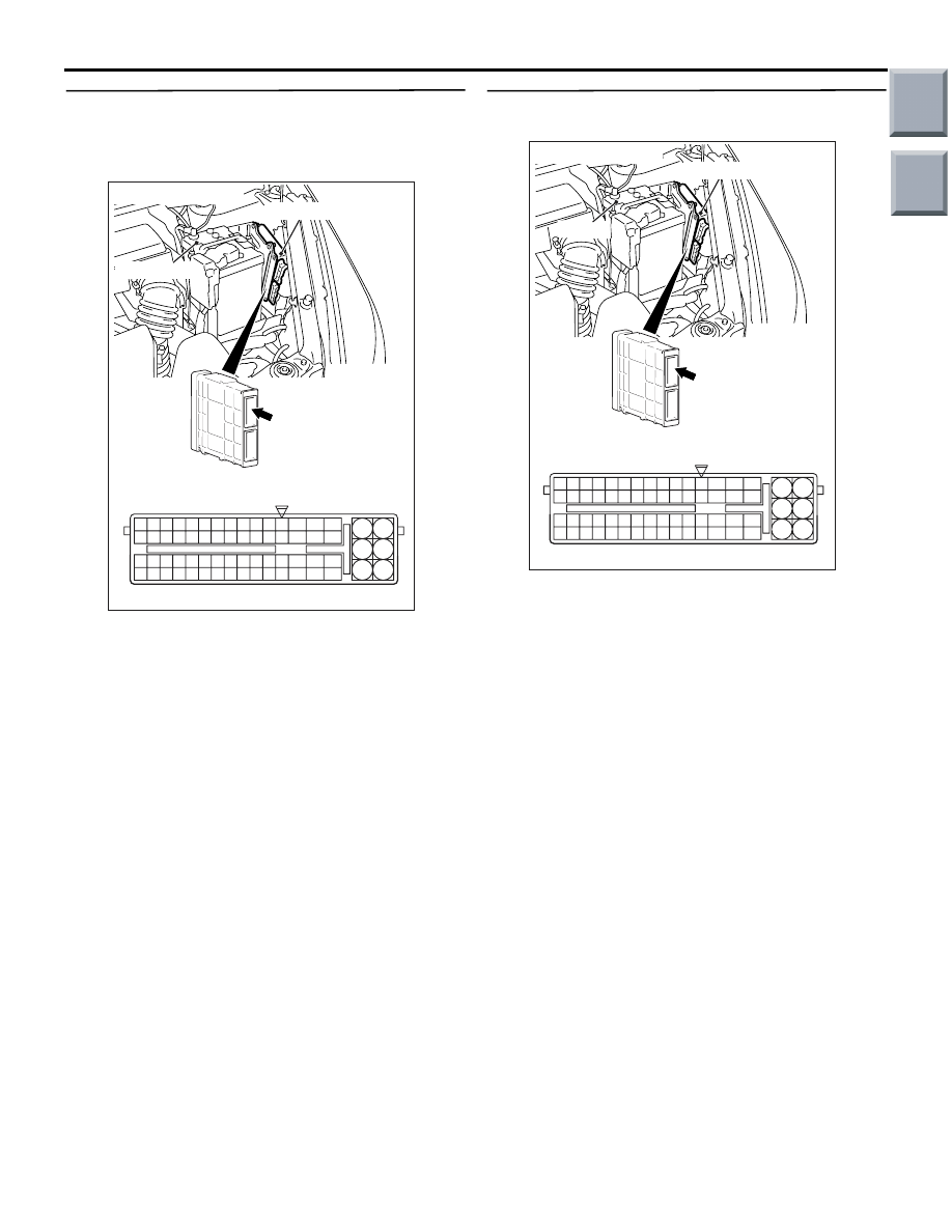
STEP 5. Measure the voltage at engine-CVT-ECU
connector A-114.
(1) Connect CVT control solenoid valve assembly
connector A-117.
AC403088AF
A-114
Connector: A-114
6
4
2
5
3
1
9
7
8
10
11
12
13
14
15
16
17
18
19
20
21
22
23
24
25
26
27
28
29
30
31
32
33
34
35
36
37
38
39
40
41
42
43
44
45
46
47
48
49
50
51
52
53
54
55
56
57
58
59
60
61
62
63
64
65
66
L
A-114 Check connector (special tool)
Engine-CVT-ECU
Battery
(GR)
(2) Disconnect the engine-CVT-ECU connector, and
connect the special tool Power plant ECU check
harness (MB991987).
(3) Let the engine run at idle.
(4) Shift the selector lever to the P range.
(5) Use the special tool Check connector to measure
the voltage between engine-CVT-ECU connector
A-114 terminal No.1 and earth.
OK: System voltage
Q: Is the check result normal?
YES : .
Go to Step 8.
NO : .
Go to Step 6.
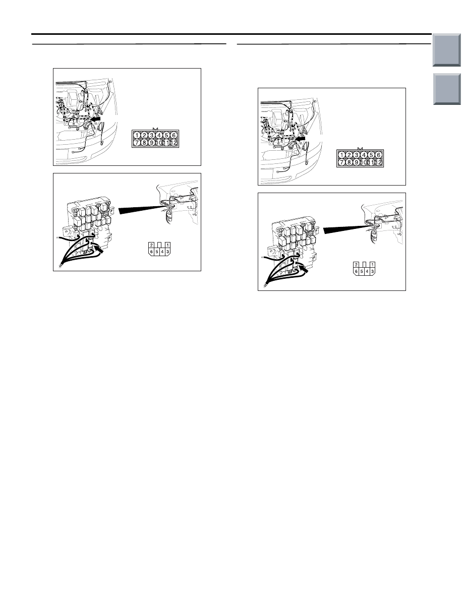
STEP 6. Connector check: A-114
engine-CVT-ECU connector.
AC403088AG
A-114
Connector: A-114
6
4
2
5
3
1
9
7
8
10
11
12
13
14
15
16
17
18
19
20
21
22
23
24
25
26
27
28
29
30
31
32
33
34
35
36
37
38
39
40
41
42
43
44
45
46
47
48
49
50
51
52
53
54
55
56
57
58
59
60
61
62
63
64
65
66
L
A-114 Harness side connector
Engine-CVT-ECU
Battery
(GR)
Check for the contact with terminals.
Q: Is the check result normal?
YES :
Go to Step 7.
NO :
Repair the defective connector.
Main
Index
Group
TOC

TROUBLESHOOTING <CVT>
CVT
23A-88
STEP 7. Check the harness between CVT control
solenoid valve assembly connector A-117
terminal No.3 and engine-CVT-ECU connector
A-114 terminal No.1.
AC314190
AC
Inhibitor switch
Transmission
control cable
A-117 (GR)
Connector: A-117
Harness side
AC403088AG
A-114
Connector: A-114
6
4
2
5
3
1
9
7
8
10
11
12
13
14
15
16
17
18
19
20
21
22
23
24
25
26
27
28
29
30
31
32
33
34
35
36
37
38
39
40
41
42
43
44
45
46
47
48
49
50
51
52
53
54
55
56
57
58
59
60
61
62
63
64
65
66
L
A-114 Harness side connector
Engine-CVT-ECU
Battery
(GR)
Check the output line for short-circuited or open cir-
cuit.
Q: Is the check result normal?
YES :
Go to Step 8.
NO :
Repair the wiring harness.
STEP 8. M.U.T.-III actuator test
Item 03: Damper clutch control solenoid valve
OK: Operating sound can be heard.
Q: Is the check result normal?
YES :
Intermittent malfunction (Refer to GROUP
00
− How to Cope with Intermittent
).
NO :
Replace the engine-CVT-ECU.
STEP 9. Connector check: A-117 CVT control
solenoid valve assembly connector.
AC314190
AC
Inhibitor switch
Transmission
control cable
A-117 (GR)
Connector: A-117
Harness side
Check for the contact with terminals.
Q: Is the check result normal?
YES :
Go to Step 10.
NO :
Repair the defective connector.
STEP 10. Measure the resistance at CVT control
solenoid valve assembly connector A-117.
AC314190
AC
Inhibitor switch
Transmission
control cable
A-117 (GR)
Connector: A-117
Harness side
Disconnect the connector, and measure the resist-
ance between terminal 3 and 10 at the solenoid
valve side.
OK: 2.9
− 3.5 Ω (CVT fluid temperature at
20
°C)
Q: Is the check result normal?
YES :
Go to Step 11.
NO :
Check the solenoid valve harness.
Main
Index
Group
TOC
TROUBLESHOOTING <CVT>
CVT
23A-89
STEP 11. Connectors check: A-17 intermediate
connector, B-109 J/B connector.
AC313811 AG
Connector: A-17
A-17 (B)
AC313824AP
Connector: B-109
Harness side
Junction block (Front view)
Check for the contact with terminals.
Q: Is the check result normal?
YES :
Go to Step 12.
NO :
Repair the defective connector.
STEP 12. Check the harness between CVT
control solenoid valve assembly connector A-117
terminal No.10 and J/B connector B-109 terminal
No.5.
AC313811 AG
Connector: A-17
A-17 (B)
AC313824AP
Connector: B-109
Harness side
Junction block (Front view)
Check the power supply line for short-circuited or
open circuit.
Q: Is the check result normal?
YES :
Go to Step 8.
NO :
Repair the wiring harness.
Main
Index
Group
TOC

TROUBLESHOOTING <CVT>
CVT
23A-90
Code No.34, 38 Clutch Pressure Control Solenoid Valve System
SOLENOID VALVE SYSTEM CIRCUIT
Refer to
.
OPERATION
The clutch pressure control solenoid valve controls
the fluid pressure to the forward clutch and the
reverse brake by using signals from the
engine-CVT-ECU.
DIAGNOSIS CODE SET CONDITIONS
• If the clutch pressure control solenoid valve driv-
ing voltage is 3 V or less, code No.34 will be set.
• If the difference between the primary speed sen-
sor output and the turbine speed sensor output is
100 r/min or less when code No.34 is set, code
No.38 will be set.
PROBABLE CAUSES
• Malfunction of clutch pressure control solenoid
valve
• Damaged harness wires and connectors
• Malfunction of the engine-CVT-ECU
DIAGNOSIS PROCEDURE
STEP 1. M.U.T.-III diagnosis code
Q: Are diagnosis codes 32, 36 set?
YES :
Go to Step 9.
NO :
Go to Step 2.
STEP 2. M.U.T.-III actuator test
Item 04: Clutch pressure control solenoid valve
OK: Operating sound can be heard.
Q: Is the check result normal?
YES :
Intermittent malfunction (Refer to GROUP
00
− How to Cope with Intermittent
).
NO :
Go to Step 3.
STEP 3. Connector check: A-117 CVT control
solenoid valve assembly connector.
AC314190
AC
Inhibitor switch
Transmission
control cable
A-117 (GR)
Connector: A-117
Harness side
Check for the contact with terminals.
Q: Is the check result normal?
YES :
Go to Step 4.
NO :
Repair the defective connector.
STEP 4. Measure the resistance at CVT control
solenoid valve assembly connector A-117.
AC314190
AC
Inhibitor switch
Transmission
control cable
A-117 (GR)
Connector: A-117
Harness side
Disconnect the connector, and measure the resist-
ance between terminal 4 and 9 at the solenoid valve
side.
OK: 2.9
− 3.5 Ω (CVT fluid temperature at
20
°C)
Q: Is the check result normal?
YES :
Go to Step 5.
NO :
Replace the clutch pressure control
solenoid valve. (Refer to
Main
Index
Group
TOC
Нет комментариевНе стесняйтесь поделиться с нами вашим ценным мнением.
Текст