Mitsubishi Colt Ralliart. Manual — part 647

ON-VEHICLE SERVICE
ENGINE MECHANICAL <4G1>
11C-8
ON-VEHICLE SERVICE
DRIVE BELT TENSION CHECK AND
ADJUSTMENT
M1111003101400
ALTERNATOR DRIVE BELT TENSION
CHECK
Check the drive belt tension in the following proce-
dure.
Standard value:
Item
When
checked
When
adjusted
When
replaced
Vibration
frequency
Hz
218
− 266
231
− 255 308 − 344
Tension N
392
− 588
441
− 539 785 − 981
Deflection
mm
(Reference)
6.3
− 8.0
6.6
− 7.5
4.1
− 5.0
<When the vibration frequency is
measured {Special tool (MB992080) is
used}: Recommendation>
NOTE: The vibration frequency measuring method is
recommended for check and adjustment of the drive
belt tension.
AC507219AB
MB992082
MB992081
Belt tension meter set (MB992080)
1. Connect the Special tool microphone assembly
(MB992082) to the Special tool belt tension meter
(MB992081) of the Special tool belt tension meter
set (MB992080).
2. Press the "POWER" button to turn on the power
supply.
3. Press number key 1. Check to ensure that "No.
01" appears on the upper left of the display and
that the following numeric values are displayed for
individual items (M, W, and S):
M 000.9 g/m
W 010.0 mm/R
S 0100 mm
If numeric values have not been entered (new
tool), set them according to the belt specifications
as shown below. Once you set them, you do not
have to set them again. The settings remain
undeleted even after battery replacement.
NOTE: This operation is to temporarily set the
preset data such as the belt specifications,
because if the measurement is taken without input
of the belt specifications, conversion to tension
value (N) cannot be made, resulting in judgement
of error.
<Setting procedure>
(1) Press down the "MASS" button till the belt
mass select display appears.
(2) Press the "UP" or "DOWN" button to select "01
1.5GT 0.9" and press the "MEASURE" button
to decide it.
Check to ensure that "M 000.9 g/m" is
displayed.
(3) Press the "WIDTH" button to change to the
belt width input display.
(4) Press number keys 0, 1, 0, and 0 sequentially,
and press the "SELECT" button to apply them.
Check to ensure that "W 010.0 mm/R"
appears on the display.
(5) Press the "SPAN" button to change to the
span length input display.
(6) Press number keys 0, 1, 0, and 0 sequentially,
and press the "SELECT" button to apply them.
Check to ensure that "S 0100 mm" appears on
the display.
4. Press "Hz" button twice to change the display to
the frequency display (Hz).
Main
Index
Group
TOC

ON-VEHICLE SERVICE
ENGINE MECHANICAL <4G1>
11C-9
CAUTION
•
AK600562
15˚
15˚
10 – 15 mm
Crankshaft
pulley
AB
Alternator
pulley
Water pump
pulley
MB992080
(Microphone)
The temperature of the surface of the belt should
be as close as possible to normal tempera-
ture.
• Do not let any contaminants such as water or
oil get onto the microphone.
• If strong gusts of wind blow against the
microphone or if there is loud sources of
noise nearby, the values measured by the
microphone may not correspond to actual
values.
• If the microphone is touching the belt while
the measurement is being made, the values
measured by the microphone may not corre-
spond to actual values.
• Do not take the measurement while the vehi-
cle's engine is running.
5. Hold the microphone to the middle of the drive
belt between the pulleys (at the place indicated by
the arrow), about 10
− 15 mm away from the rear
surface of the belt and so that it is perpendicular
to the belt (within an angle of
± 15 °).
6. Press the "MEASURE" button.
7. Gently tap the middle of the belt between the
pulleys (the place indicated by the arrow) with
your finger as shown in the illustration, and check
that the vibration frequency of the belt is within the
standard value.
NOTE: To take the measurement repeatedly, fillip
the belt again.
8. After the completion of the measurement, press
and hold the "POWER" button to turn off the
power supply.
<When the vibration frequency is
measured vehicle communication
interface (V.C.I.) is used:
Recommendation>
NOTE: The vibration frequency measuring method is
recommended for check and adjustment of the drive
belt tension.
AK600561
AB
MB991668
MB991824
MB991910
Diagnosis
connector
CAUTION
To prevent damage to special tool V.C.I.
(MB991824), always turn the ignition switch to
the "LOCK" (OFF) position before connecting or
disconnecting special tool V.C.I. (MB991824).
1. Connect the special tool belt tension meter set
(MB991668) to the special tool V.C.I (MB991824).
2. Connect special tool M.U.T.-III main harness A
(MB991910) to special tool V.C.I. (MB991824).
3. Connect special tool M.U.T.-III main harness A
(MB991910) to the diagnosis connector.
4. Turn the ignition switch to the "ON" position and
select "Belt Tension Measurement" from the menu
screen.
Main
Index
Group
TOC
ON-VEHICLE SERVICE
ENGINE MECHANICAL <4G1>
11C-10
CAUTION
• The temperature of the surface of the belt
should be as close as possible to normal tem-
perature.
• Do not let any contaminants such as water or
oil get onto the microphone.
• If strong gusts of wind blow against the
microphone or if there is loud sources of
noise nearby, the values measured by the
microphone may not correspond to actual
values.
• If the microphone is touching the belt while
the measurement is being made, the values
measured by the microphone may not corre-
spond to actual values.
• Do not take the measurement while the vehi-
cle's engine is running.
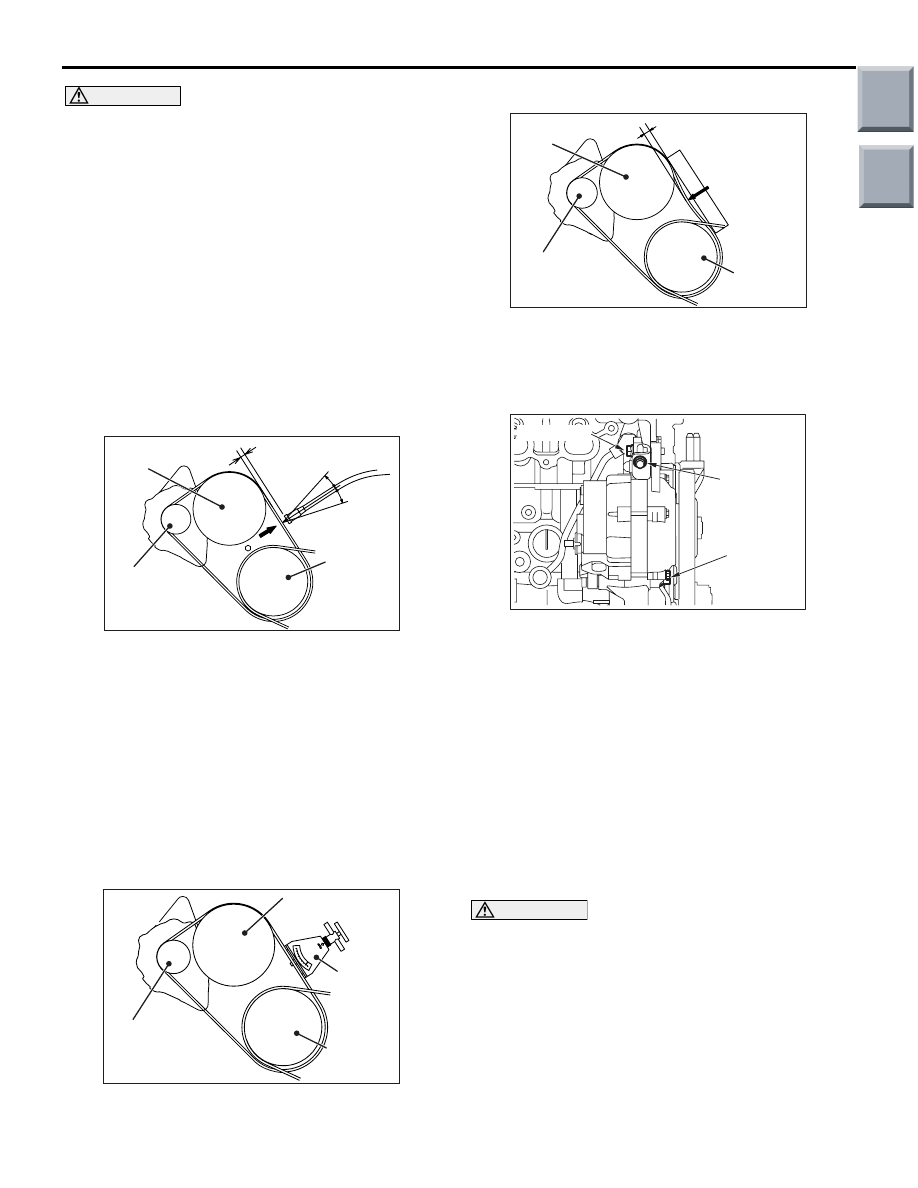
AK402044
15˚
15˚
MB991668
(Microphone)
10 – 20 mm
Crankshaft
pulley
AC
Alternator
pulley
Water pump
pulley
5. Hold the microphone to the middle of the drive
belt between the pulleys (at the place indicated by
the arrow), about 10
− 20 mm away from the rear
surface of the belt and so that it is perpendicular
to the belt (within an angle of
± 15 °).
6. Gently tap the middle of the belt between the
pulleys (the place indicated by the arrow) with
your finger as shown in the illustration, and check
that the vibration frequency of the belt is within the
standard value.
<When using the tension gauge>
AK402045
Tension
Gauge
Crankshaft
pulley
AC
Alternator
pulley
Water pump
pulley
Use a belt tension gauge to check that the belt ten-
sion is within the standard value.
<Belt deflection check>
AK402046
Approximately
100 N
Crankshaft
pulley
AC
Alternator
pulley
Water pump
pulley
Deflection
Apply approx. 100 N of force to the middle of the
drive belt between the pulleys (at the place indicated
by the arrow) and check that the amount of deflection
is within the standard value.
AC402698
Adjusting
bolt
Nut
Locking bolt
AC
If not within the standard value, adjust the belt ten-
sion by the following procedure.
1. Loosen the nut of the alternator pivot bolt.
2. Loosen the lock bolt.
3. Use the adjusting bolt to adjust the belt tension
and belt deflection to the standard values.
4. Tighten the nut of the alternator pivot bolt.
Tightening torque: 44
± 10 N⋅m
5. Tighten the nut of the lock bolt.
Tightening torque: 23
± 2 N⋅m
6. Tighten the adjusting bolt.
Tightening torque: 5.0
± 1.0 N⋅m
CAUTION
When checking the belt tension, turn the crank-
shaft clockwise one turn or more.
7. Check the belt tension, and readjust if necessary.
8. When the belt tension is adjusted by measuring
the deflection, adjust it with a tool for vibration
frequency measurement or tension measurement
afterward.
Main
Index
Group
TOC

ON-VEHICLE SERVICE
ENGINE MECHANICAL <4G1>
11C-11
A/C COMPRESSOR DRIVE BELT TEN-
SION CHECK AND ADJUSTMENT
AC205664AB
Tensioner
pulley
Crankshaft pulley
A/C compressor
pulley
Check the drive belt tension by the following proce-
dures.
Standard value:
Item
When
checked
When
adjusted
When
replaced
Vibration
frequency Hz
165
− 213 179 − 203 213 − 253
Tension N
294
− 490 343 − 441 490 − 686
Deflection
mm
(Reference)
8.9
− 11.2 9.3 − 10.7 6.6 − 8.6
<When the vibration frequency is
measured: Recommendation>
Gently tap the centre of the belt between the pulleys
(arrow), and check that the belt vibration frequency is
within the standard value.
<When tension is measured>
Place a belt tension gauge at the centre of the belt
between the pulleys (arrow), and check that the belt
tension is within the standard value.
<When deflection is measured>
Apply approx. 100 N of pressure against the location
between the pulleys shown by the arrow in the illus-
tration and then measure the deflection.
If not within the standard value, adjust the belt ten-
sion by the following procedure.
AC205665AB
Adjusting bolt
Tensioner
pulley
Locking nut
1. Loosen the locking nut of the tensioner pulley.
2. Use the adjusting bolt to adjust the belt tension.
The tension will increase when turning the
adjusting bolt clockwise, and decrease when
turning anti-clockwise.
3. Tighten the locking nut of the tensioner pulley at
the specified torque.
Tightening torque: 48
± 6 N⋅m
4. Tighten the adjusting bolt at the specified torque.
Tightening torque: 5.0
± 1.0 N⋅m
CAUTION
When checking the belt tension, turn the crank-
shaft clockwise one turn or more.
5. Check the belt tension, and readjust if necessary.
6. When the belt tension is adjusted by measuring
the deflection, adjust it with a tool for vibration
frequency measurement or tension measurement
afterward.
Main
Index
Group
TOC
Нет комментариевНе стесняйтесь поделиться с нами вашим ценным мнением.
Текст