Mitsubishi Colt Ralliart. Manual — part 103
ON-VEHICLE SERVICE
MULTIPORT FUEL INJECTION (MPI) <4A9>
13A-366
MEASUREMENT OF RESISTANCE
BETWEEN TERMINALS
1. Disconnect the oil feeder control valve connector.
2. Measure the resistance between the terminals of
the connector at the oil feeder control valve.
Standard value: 6.9
− 7.9 Ω (at 20°C)
3. If resistance is outside the standard value, replace
the oil feeder control valve.
THROTTLE VALVE CONTROL SERVO
CHECK
M1131051000326
OPERATION CHECK
1. Remove the air intake hose from the throttle body.
2. Turn the ignition switch to ON position.
3. Operate the accelerator pedal and confirm that
the throttle valve is opening and closing
accordingly.
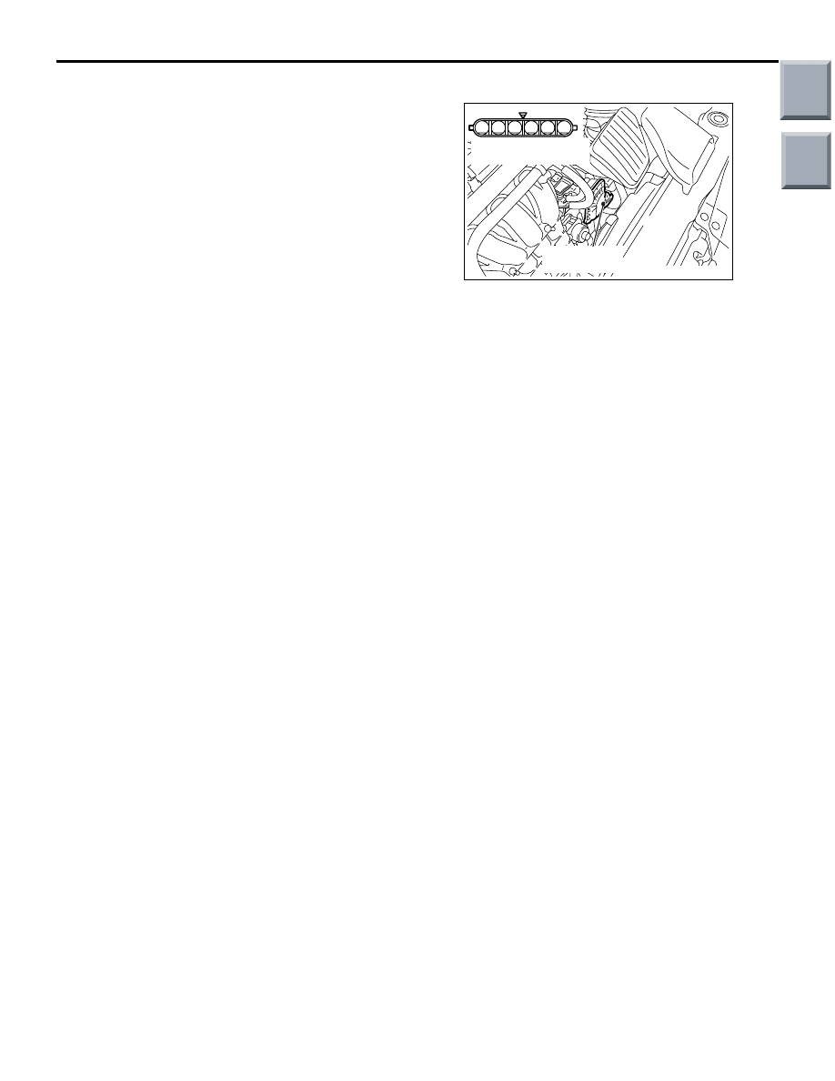
CHECK THE COIL RESISTANCE
1. Disconnect the electronic-controlled throttle valve
connector.
2. Measure the resistance between terminals No. 1
and No. 2 at the electronic-controlled throttle
valve connector.
Standard value: 0.3
− 100 Ω (at 20°C)
3. If the resistance is outside the standard value,
replace the throttle body assembly.
AK402206
6
1 2 3 4 5
AC
Throttle valve
control servo
Throttle valve control
servo side connector
Main
Index
Group
TOC
INJECTOR
MULTIPORT FUEL INJECTION (MPI) <4A9>
13A-367
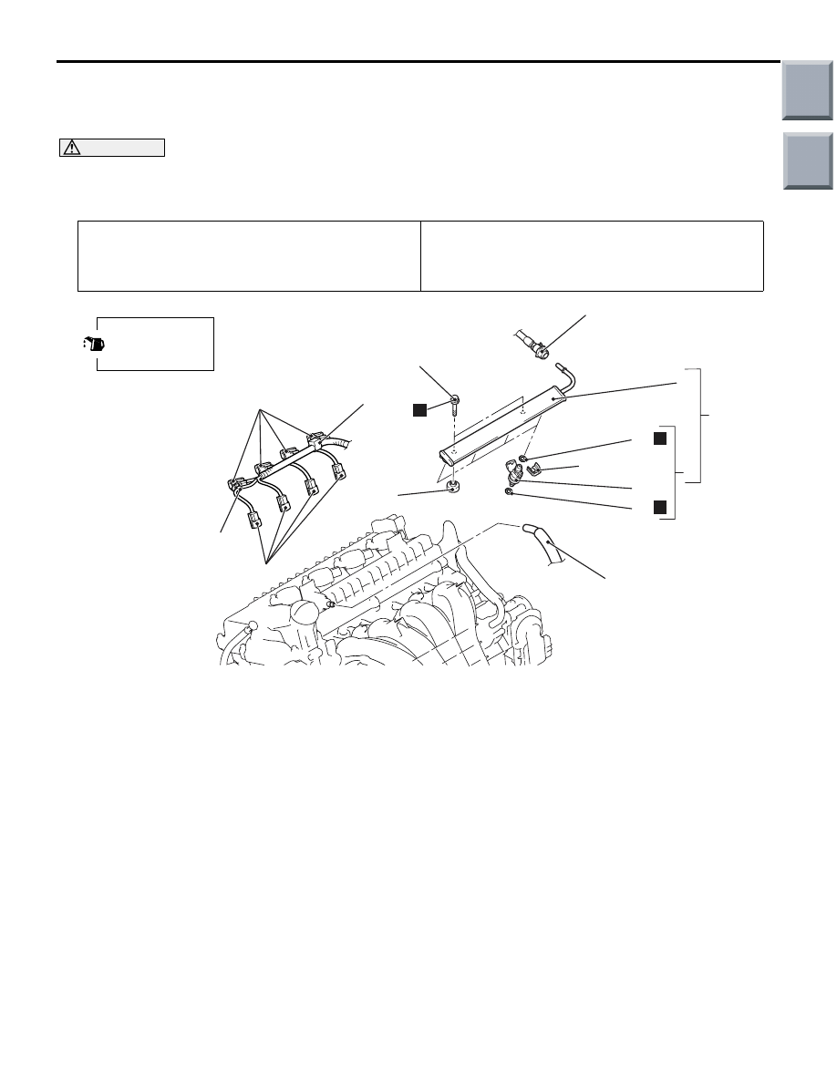
INJECTOR
REMOVAL AND INSTALLATION
M1131007101620
CAUTION
When the fuel injector replacement is performed, use the M.U.T.-III to initialize the learning value
(Refer to GROUP 00, Precautions Before Service
− Initialization Procedure for Learning Value in MPI
Engine
Pre-removal Operation
• Fuel Discharge Prevention (Refer to
).
• Engine Cover Removal (Refer to GROUP 11A, Camshaft
Post-installation Operation
• Fuel Leakage Inspection
• Engine Cover Installation (Refer to GROUP 11A, Cam-
shaft
AC312110
11
6
1
2
4
3
5
7
8
9
10
12
13
18 ± 1 N·m
4
N
N
AC
Apply engine oil to
the O-ring before
installation.
N
Removal steps
1.
PCV hose connection
2.
Ignition coil connector
3.
Fuel injector connector
4.
Control harness clamp connection
<<
A
>> >>
E
<< 5.
Fuel high-pressure hose
connection
>>
D
<< 6.
Fuel delivery pipe and fuel injector
assembly
7.
Fuel injector insulator
>>
C
<< 8.
Fuel injector support
>>
B
<< 9.
Fuel injector assembly
>>
A
<< 10. O-ring
>>
A
<< 11. O-ring
12. Fuel injector
13. Fuel delivery pipe
Removal steps (Continued)
Main
Index
Group
TOC

INJECTOR
MULTIPORT FUEL INJECTION (MPI) <4A9>
13A-368
REMOVAL SERVICE POINT
<<A>> FUEL HIGH-PRESSURE HOSE
DISCONNECTION
1. Remove the stopper.
2. Raise the retainer, and pull out the fuel
high-pressure hose.
NOTE: If the retainer comes off, install it securely
after pulling out the fuel high-pressure hose.
INSTALLATION SERVICE POINTS
>>A<< O-RING INSTALLATION
1. Apply a small amount of new engine oil to the
O-ring.
2. While turning the fuel injector to the right and left,
install the O-ring to the fuel injector with care not
to damage the O-ring.
>>B<< FUEL INJECTOR ASSEMBLY
INSTALLATION
CAUTION
Do not let the engine oil get into the fuel delivery
pipe will be damaged.
1. Apply a drop of new engine oil to the O-ring.
2. Turn the fuel injector assembly to the right and left
to install to the fuel delivery pipe. Be careful not to
damage the O-ring. After installing, check that the
item turns smoothly.
3. If it does not turn smoothly, the O-ring may be
trapped, remove the fuel injector assembly,
re-install it into the fuel delivery pipe and check
again.
4. Install the fuel injector assembly so that the
convex portion of the fuel injector is located at the
centre of the fuel delivery pipe brim.
>>C<< FUEL INJECTOR SUPPORT
INSTALLATION
Install the fuel injector support to the fuel injector
groove and fuel delivery pipe brim, and fix the fuel
injector assembly and fuel delivery pipe.
AC403077AB
Fuel high-pressure
hose
Stopper
AC403078 AB
Fuel high-pressure
hose
Retainer
AC312107
AB
(Engine oil)
O-ring
Fuel injector
O-ring
AC312108
AC
Fuel delivery
pipe brim
Fuel injector
protrusion
AC312109
AC
Fuel delivery
pipe brim
Fuel injector
support
Fuel injector
groove
Main
Index
Group
TOC

INJECTOR
MULTIPORT FUEL INJECTION (MPI) <4A9>
13A-369
>>D<< FUEL DELIVERY PIPE AND FUEL
INJECTOR ASSEMBLY INSTALLATION
CAUTION
Do not let the engine oil get into the engine will
be damaged.
1. Apply a small amount of new engine oil to the
O-ring at the tip of the fuel injector assembly.
CAUTION
When installing the fuel delivery pipe and fuel
injector assembly to the cylinder head, take care
not to damage the O-ring at the tip of the fuel
injector assembly.
2. Install the fuel delivery pipe and fuel injector
assembly to the cylinder head. Be careful not to
damage the O-ring.
3. Tighten the new fuel delivery pipe mounting bolts
to the specified torque.
Tightening torque: 18
± 1 N⋅m
>>E<< FUEL HIGH-PRESSURE HOSE
CONNECTION
CAUTION
• After connecting the fuel high-pressure hose,
check that it has been securely installed by
slightly pulling in the removal direction. At
this time, also check that there is approxi-
mately 3-mm play.
• Do not let the engine oil get into the fuel deliv-
ery pipe will be damaged.
Apply a small amount of new engine oil to the fuel
delivery pipe, and install the fuel high-pressure hose
to the fuel delivery pipe.
AC208465AE
3 mm
Fuel high-pressure hose
Fuel delivery pipe
Main
Index
Group
TOC
Нет комментариевНе стесняйтесь поделиться с нами вашим ценным мнением.
Текст