Mitsubishi Colt Ralliart. Manual — part 308
TROUBLESHOOTING
CONTROLLER AREA NETWORK (CAN)
54D-61
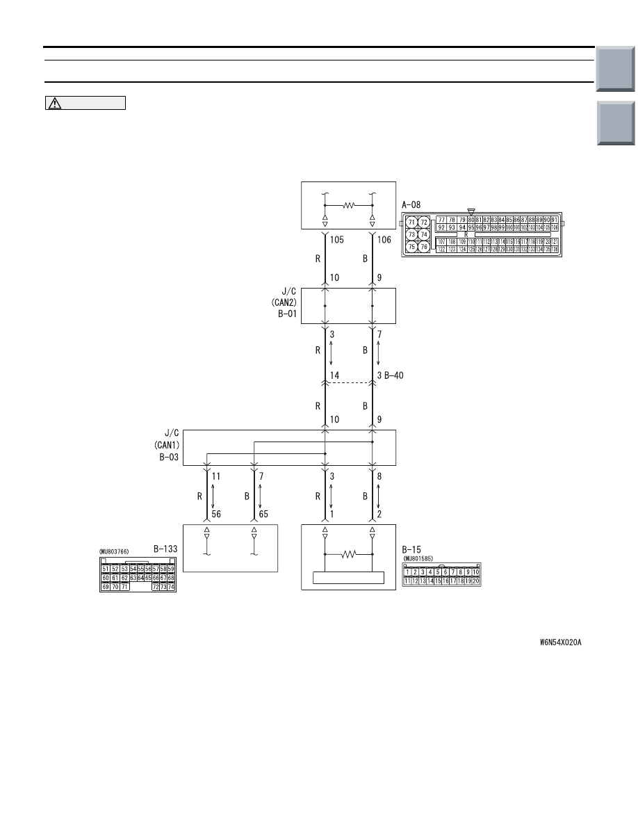
Diagnosis Item 6: Diagnose when the M.U.T.-III cannot receive the data sent by ETACS-ECU.
CAUTION
When servicing a CAN bus line, earth yourself by touching a metal object such as an unpainted water
pipe. If you fail to do, a component connected to the CAN bus line may be broken.
COMBINATION
METER
ETACS-
ECU
Wire colour code
B : Black LG : Light green G : Green L : Blue W : White Y : Yellow SB : Sky blue
BR : Brown O : Orange GR : Grey R : Red P : Pink V : Violet PU : Purple
ENGINE-ECU <M/T> OR
ENGINE-CVT-ECU <CVT>
FUNCTION
The diagnostic result demonstrates that "the
M.U.T.-III cannot receive the sent data from the
ETACS-ECU" when the M.U.T.-III checks the periodi-
cally sent data from each ECU and cannot receive
the ETACS-ECU data only.
TROUBLE JUDGEMENT CONDITIONS
M.U.T.-III judges the trouble when the periodically
sent data from ETACS-ECU cannot be received and
sent.
PROBABLE CAUSES
• Damaged harness wires and connectors
• Power supply circuit malfunction of the
ETACS-ECU
• Malfunction of the ETACS-ECU
Main
Index
Group
TOC
TROUBLESHOOTING
CONTROLLER AREA NETWORK (CAN)
54D-62
DIAGNOSIS PROCEDURE
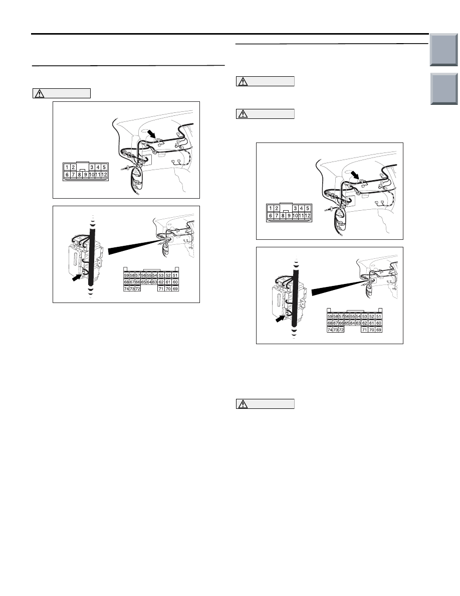
STEP 1. Connector check: B-03 joint connector
(CAN1) and B-133 ETACS-ECU connector
AC313820
Connector: B-03
AE
AC313826 AB
Connector: B-133
Harness side
B-133 (GR)
CAUTION
The strand end of the twist wire should be within
10 cm from the connector. For details refer to
.
When checking the joint connector, ensure that its
wiring harness side and its short pins are not dam-
aged.
Q: Is the check result normal?
YES :
Go to Step 2.
NO :
Repair the defective connector. Replace the
joint connector as necessary.
STEP 2. Resistance measurement at B-03 joint
connector (CAN1) and B-133 ETACS-ECU
connector.
CAUTION
A digital multimeter should be used. For details
refer to
CAUTION
The test wiring harness should be used. For
details refer to
.
AC313820
Connector: B-03
AE
AC313826 AB
Connector: B-133
Harness side
B-133 (GR)
(1) Disconnect the joint connector (CAN1) and the
ETACS-ECU connector, and measure at the
wiring harness side.
(2) Turn the ignition switch to the OFF (LOCK)
position.
CAUTION
When measuring the resistance, disconnect the
negative battery terminal. For details refer to
.
(3) Ensure that the negative battery terminal is
disconnected.
Main
Index
Group
TOC
AC313937
Harness side: B-03
Harness side: B-133
AP
Test
harness
Test
harness
TROUBLESHOOTING
CONTROLLER AREA NETWORK (CAN)
54D-63
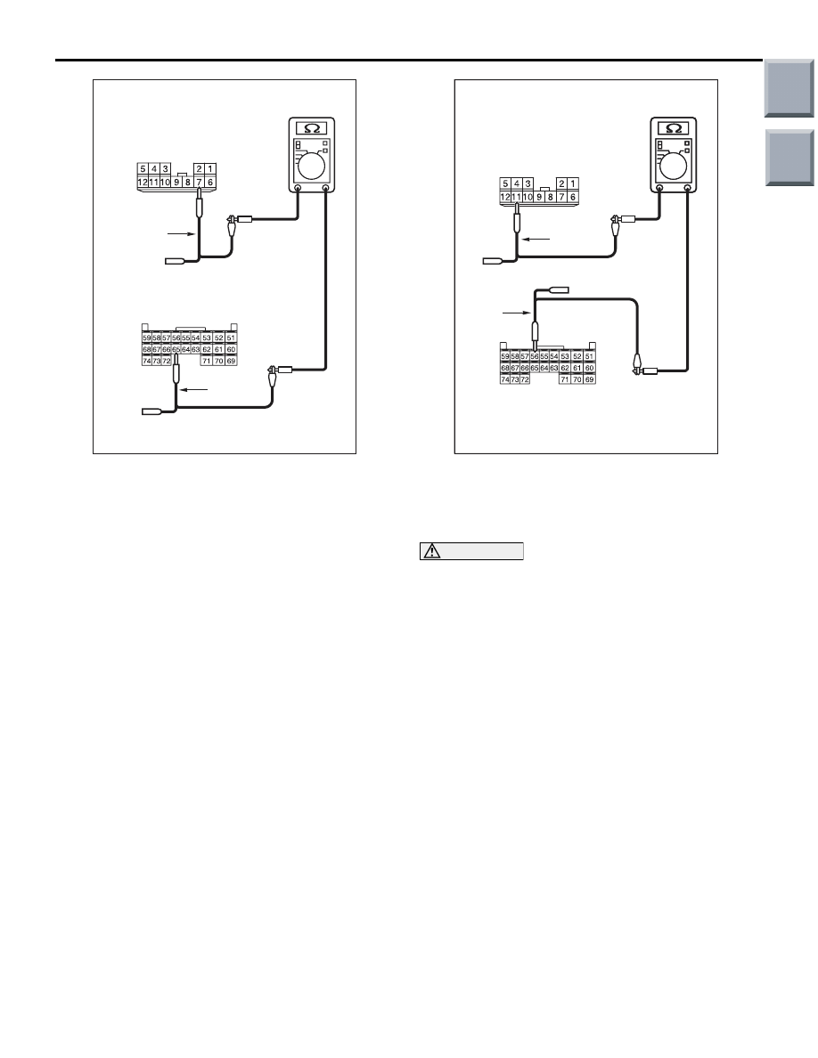
(4) Continuity between B-03 joint connector (CAN1)
terminal No.7 and B-133 ETACS-ECU connector
terminal No.65
OK: Continuity (2
Ω or less)
AC313937
AC313937
Harness side: B-03
Harness side: B-133
Test
harness
AQ
Test
harness
(5) Continuity between B-03 joint connector (CAN1)
terminal No.11 and B-133 ETACS-ECU
connector terminal No.56
OK: Continuity (2
Ω or less)
CAUTION
Strictly observe the specified wiring harness
repair procedure. For details refer to
Q: Is the check result normal?
YES :
<All the resistances measure 2
Ω or less>
Power supply to the ETACS-ECU may be
suspected. Diagnose the SWS. Refer to
GROUP 54B
− Troubleshooting
NO :
<Either or all of the resistances measure
more than 2
Ω> Repair the wiring harness
between joint connector (CAN1) and the
ETACS-ECU connector.
Main
Index
Group
TOC
TROUBLESHOOTING
CONTROLLER AREA NETWORK (CAN)
54D-64
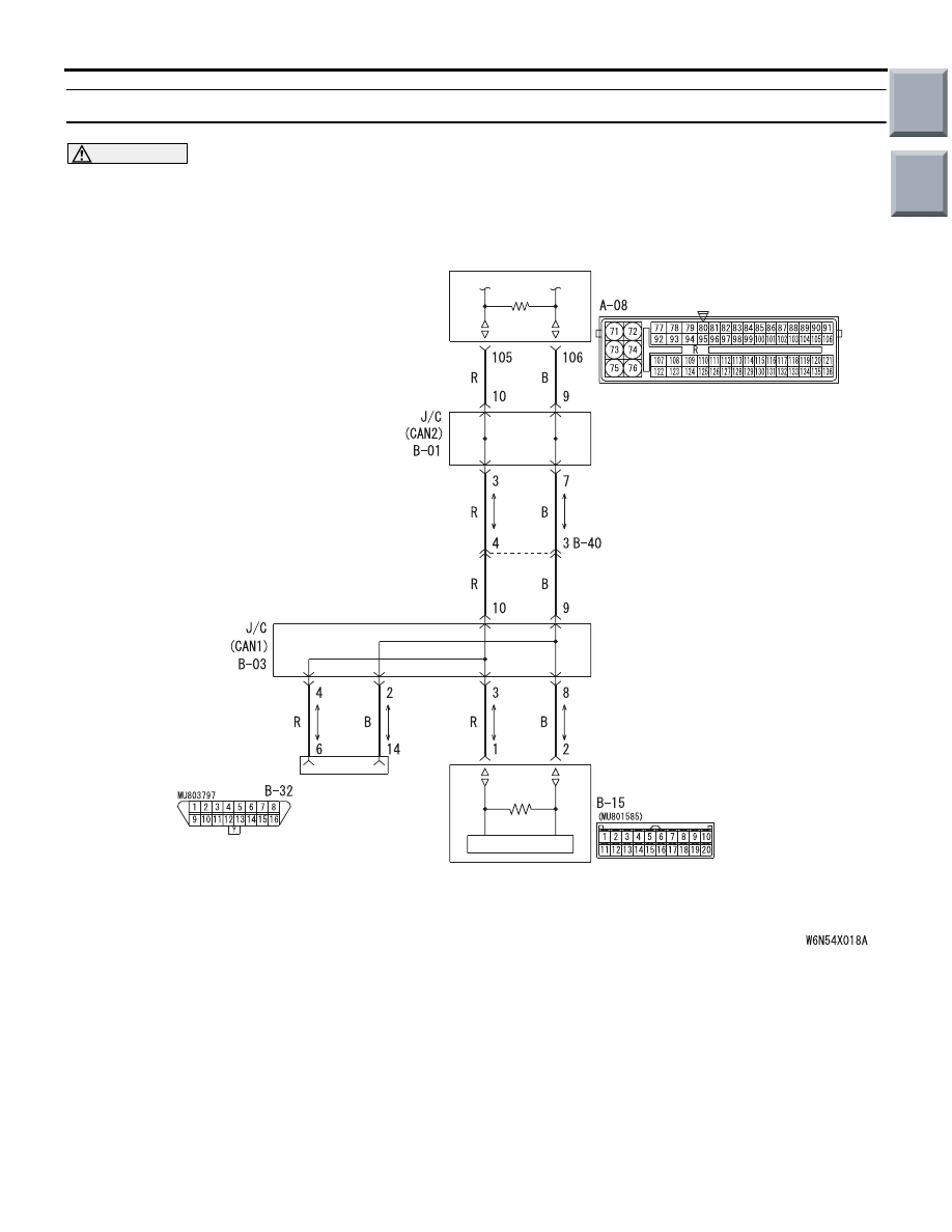
Diagnostic Item 7: Diagnose the lines between the joint connectors (CAN1 and CAN2).
CAUTION
When servicing a CAN bus line, earth yourself by touching a metal object such as an unpainted water
pipe. If you fail to do, a component connected to the CAN bus line may be broken.
ENGINE-ECU <M/T> OR
ENGINE-CVT-ECU <CVT>
COMBINATION
METER
DIAGNOSIS
CONNECTOR
Wire colour code
B : Black LG : Light green G : Green L : Blue W : White Y : Yellow SB : Sky blue
BR : Brown O : Orange GR : Grey R : Red P : Pink V : Violet PU : Purple
FUNCTION
The diagnostic result demonstrates that "diagnose
the lines between the joint connectors (CAN1 and
CAN2)" when the M.U.T.-III checks the periodically
sent data from each ECU and cannot receive the
engine-A/T-ECU, the ABS-ECU, the A/C-ECU and
the SRS-ECU data.
TROUBLE JUDGEMENT CONDITIONS
M.U.T.-III judges the trouble when the periodically
sent data from EPS-ECU, G and yaw rate sensor
<vehicles with ASC>, ABS-ECU <vehicles without
ASC> or ASC-ECU <vehicles with ASC> and the
engine-ECU <M/T> or engine-CVT-ECU <CVT> can-
not be received and sent.
PROBABLE CAUSE
Damaged harness wires and connectors
Main
Index
Group
TOC
Нет комментариевНе стесняйтесь поделиться с нами вашим ценным мнением.
Текст