Mitsubishi Colt Ralliart. Manual — part 356

SYMPTOM PROCEDURES
SMART WIRING SYSTEM (SWS) NOT USING SWS MONITOR
54B-168
Step 5. Pulse check
Check the input signals below, which are related to
the turn-signal lamp illumination.
OK: The M.U.T.-III sounds or the voltmeter
needle fluctuates.
Q: Are the check result normal?
All the signals are received normally. :
Go to Step
6.
The turn-signal lamp switch (RH) signal is not
received. :
Refer to Inspection Procedure N-4
"The column switch (lighting and turn-signal
lamp switch) signal is not received
."
The turn-signal lamp switch (LH) signal is not
received. :
Refer to Inspection Procedure N-4
"The column switch (lighting and turn-signal
lamp switch) signal is not received
."
Step 6. Retest the system.
Check that the turn-signal lamps illuminate.
Q: Is the check result normal?
YES :
The trouble can be an intermittent
malfunction (Refer to GROUP 00
− How to
use Troubleshooting/inspection Service
Points
− How to Cope with Intermittent
).
NO :
Replace the ETACS-ECU.
System switch
Check condition
Turn-signal lamp switch
(RH)
When the turn-signal
lamp switch (RH) is
turned from off to on
Turn-signal lamp switch
(LH)
When the turn-signal
lamp switch (LH) is
turned from off to on
Main
Index
Group
TOC
SYMPTOM PROCEDURES
SMART WIRING SYSTEM (SWS) NOT USING SWS MONITOR
54B-169
INSPECTION PROCEDURE L-2: The hazard warning lamps do not illuminate.
CAUTION
Whenever the ECU is replaced, ensure that the
input and output signal circuits are normal.
COMMENTS ON TROUBLE SYMPTOM
If the hazard warning lamps do not illuminate, the
hazard warning lamp input signal circuit or the
ETACS-ECU may be defective.
POSSIBLE CAUSES
• Malfunction of the hazard warning lamp switch
• Malfunction of the ETACS-ECU
• Damaged harness wires and connectors
DIAGNOSIS PROCEDURE
Step 1. Check that the turn-signal lamps operate.
Check that the turn-signal lamps illuminate normally.
Q: Is the check result normal?
YES :
Go to Step 2.
NO :
Refer to Inspection Procedure L-1 "The turn
signal lamps do not illuminate
Wire colour code
B : Black LG : Light green G : Green L : Blue W : White Y : Yellow SB : Sky blue
BR : Brown O : Orange GR : Gray R : Red P : Pink V : Violet
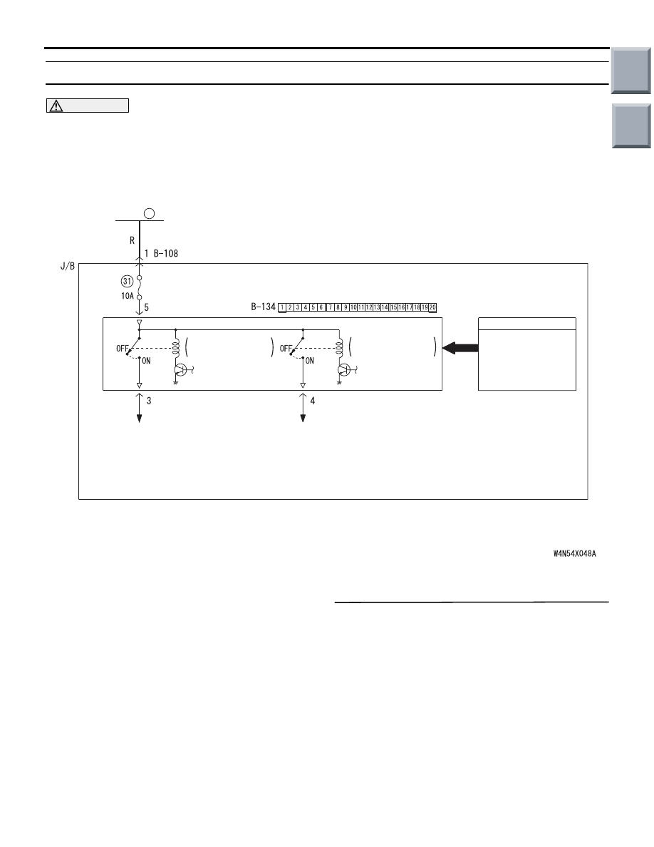
ETACS-ECU
HAZARD
WARNING
LAMP SWITCH
TURN-SIGNAL
LAMP RELAY: LH
TURN-SIGNAL
LAMP RELAY: RH
INPUT SIGNAL
· FRONT COMBINATION
LAMP (TURN: LH)
· SIDE TURN-SIGNAL
LAMP (LH)
· REAR COMBINATION
LAMP (TURN: LH)
· FRONT COMBINATION
LAMP (TURN: RH)
· SIDE TURN-SIGNAL
LAMP (RH)
· REAR COMBINATION
LAMP (TURN: RH)
FUSIBLE
LINK
1
Hazard Warning Lamp Circuit
Main
Index
Group
TOC

SYMPTOM PROCEDURES
SMART WIRING SYSTEM (SWS) NOT USING SWS MONITOR
54B-170
Step 2. Check the power supply circuit.
When the ignition switch is at the LOCK (OFF) posi-
tion, check that the functions below work normally.
• Lamp reminder function
• Central door locking system
• Room lamp (excluding interior lamp auto-
matic-shutdown function)
Q: Is the check result normal?
YES :
Go to Step 3.
NO :
Refer to Inspection Procedure A-2 "When
the ignition switch is at the LOCK (OFF)
position, the functions do not work normally.
Check the battery power supply circuit to
the ETACS-ECU
."
Step 3. Pulse check
Check the input signal from the hazard warning lamp
switch.
OK: The M.U.T.-III sounds or the voltmeter
needle fluctuates.
Q: Is the check result normal?
YES :
Go to Step 4.
NO :
Refer to Inspection Procedure N-9 "The
hazard warning lamp switch signal is not
received
."
Step 4. Retest the system.
Check that the hazard warning lamps illuminate.
Q: Is the check result normal?
YES :
The trouble can be an intermittent
malfunction (Refer to GROUP 00
− How to
use Troubleshooting/inspection Service
Points
− How to Cope with Intermittent
).
NO :
Replace the ETACS-ECU.
System switch
Check condition
Hazard warning lamp
switch
When the hazard
warning lamp switch is
turned from off to on
Main
Index
Group
TOC
SYMPTOM PROCEDURES
SMART WIRING SYSTEM (SWS) NOT USING SWS MONITOR
54B-171
INSPECTION PROCEDURE L-3: Any of the turn-signal lamps does not illuminate.
CAUTION
Whenever the ECU is replaced, ensure that the
input and output signal circuits are normal.
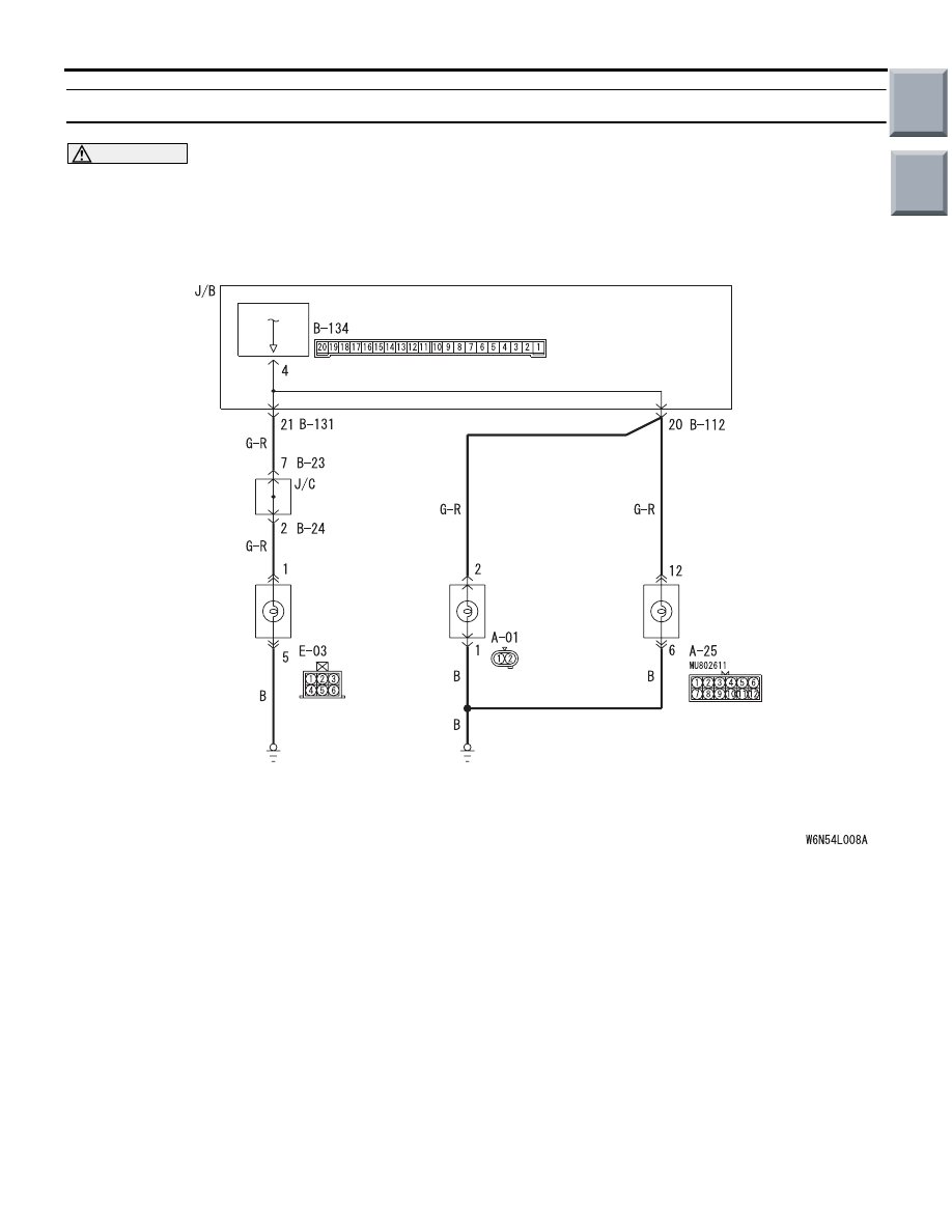
ETACS-ECU
REAR
COMBINATION
LAMP
(TURN: RH)
FRONT
COMBINATION
LAMP
(TURN: RH)
SIDE TURN
SIGNAL LAMP
(RH)
J/B SIDE
Turn-Signal Lamps Circuit (RH)
Wire colour code
B : Black LG : Light green G : Green L : Blue W : White Y : Yellow SB : Sky blue
BR : Brown O : Orange GR : Grey R : Red P : Pink V : Violet PU : Purple
Main
Index
Group
TOC
Нет комментариевНе стесняйтесь поделиться с нами вашим ценным мнением.
Текст