Mitsubishi Colt Ralliart. Manual — part 366
INPUT SIGNAL PROCEDURES
SMART WIRING SYSTEM (SWS) NOT USING SWS MONITOR
54B-208
INSPECTION PROCEDURE N-6: The windshield intermittent wiper volume signal is not received.
CAUTION
Whenever the ECU is replaced, ensure that the
input signal circuit is normal.
COMMENTS ON TROUBLE SYMPTOM
The intermittent wiper interval is calculated in
accordance with the input signal from the windshield
intermittent wiper volume. If this signal is abnormal,
the wiper interval can not be adjusted.
POSSIBLE CAUSES
• Malfunction of the column switch
• Malfunction of the ETACS-ECU
• Damaged harness wires and connectors
DIAGNOSIS PROCEDURE
Step 1. Connector check: B-135 column switch
connector.
Q: Is the check result normal?
YES :
Go to Step 2.
NO :
Repair the defective connector.
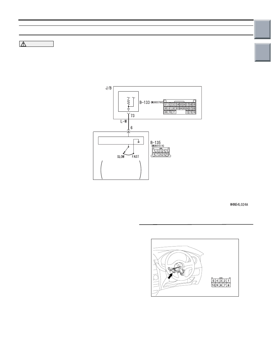
COLUMN
SWITCH
WINDSHIELD
INTERMITTENT
WIPER INTERVAL
ADJUSTING KNOB
ETACS-
ECU
COLUMN-ECU
Wire colour code
B : Black LG : Light green G : Green L : Blue W : White Y : Yellow SB : Sky blue
BR : Brown O : Orange GR : Gray R : Red P : Pink V : Violet
Windshield Intermittent Wiper Interval Adjusting Knob Input Circuit
AC401044AC
Connector: B-135
Harness side
Main
Index
Group
TOC

INPUT SIGNAL PROCEDURES
SMART WIRING SYSTEM (SWS) NOT USING SWS MONITOR
54B-209
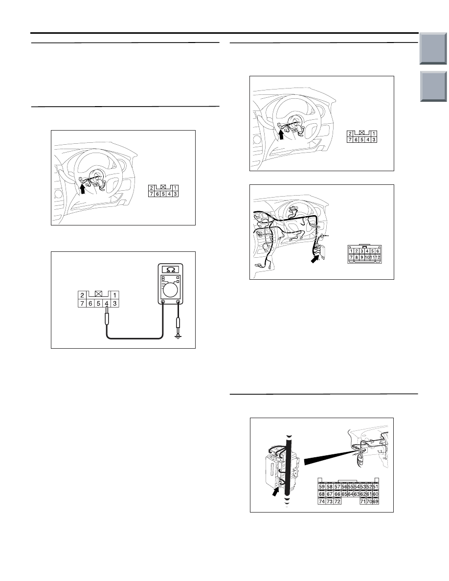
Step 2. Resistance measurement at the B-135
column switch connector.
(1) Disconnect the connector, and measure at the
column switch side.
(2) Resistance between B-135 column switch
connector terminal No.6 and body earth
OK: The resistance should rise from 0 to
1 k
Ω when the windshield intermittent
wiper volume is rotated from "Fast" to
"Slow".
Q: Is the check result normal?
YES :
Go to Step 3.
NO :
Replace the column switch.
Step 3. Connector check: B-133 ETACS-ECU
connector.
Q: Is the check result normal?
YES :
Go to Step 4.
NO :
Repair the defective connector.
Step 4. Check the wiring harness between B-135
column switch connector terminal No.6 to B-133
ETACS-ECU connector terminal No.73.
• Check the input line for open circuit.
Q: Is the check result normal?
YES :
Go to Step 5.
NO :
Repair the wiring harness.
Step 5. Retest the system.
Check that the windshield intermittent wiper volume
is sending a correct signal.
Q: Is the check result normal?
YES :
The trouble can be an intermittent
malfunction (Refer to GROUP 00
− How to
use Troubleshooting/inspection Service
Points
− How to Cope with Intermittent
).
NO :
Replace the ETACS-ECU.
AC401044AC
Connector: B-135
Harness side
AC310506 DO
Connector B-135
(Harness side)
AC313826AC
B-133 (GR)
Connector: B-133
Harness side
Junction block (Rear view)
AC313826AC
B-133 (GR)
Connector: B-133
Harness side
Junction block (Rear view)
AC401044AC
Connector: B-135
Harness side
Main
Index
Group
TOC

INPUT SIGNAL PROCEDURES
SMART WIRING SYSTEM (SWS) NOT USING SWS MONITOR
54B-210
INSPECTION PROCEDURE N-7: The key reminder switch signal is not received.
CAUTION
Whenever the ECU is replaced, ensure that the
input signal circuit is normal.
COMMENTS ON TROUBLE SYMPTOM
Input signal from the key reminder switch is used to
operate the functions below. If the signal is abnormal,
these functions will not work normally.
• Keyless entry system
• Ignition key cylinder illumination lamp
• Room lamp
POSSIBLE CAUSES
• Malfunction of the key reminder switch
• Malfunction of the ETACS-ECU
• Damaged harness wires and connectors
DIAGNOSIS PROCEDURE
Step 1. Connector check: B-140 key reminder
switch connector
Q: Is the check result normal?
YES :
Go to Step 2.
NO :
Repair the defective connector.
ETACS-
ECU
KEY
REMINDER
SWITCH
Wire colour code
B : Black LG : Light green G : Green L : Blue W : White Y : Yellow SB : Sky blue
BR : Brown O : Orange GR : Gray R : Red P : Pink V : Violet
WHEN REMOVING
KEY: ON
Key Reminder Switch Input Circuit
AC401044
Connector: B-140
AB
Harness side
B-140(B)
Main
Index
Group
TOC
INPUT SIGNAL PROCEDURES
SMART WIRING SYSTEM (SWS) NOT USING SWS MONITOR
54B-211
Step 2. Check the key reminder switch.
Refer to GROUP 54A
− Ignition switch
.
Q: Is the check result normal?
YES :
Go to Step 3.
NO :
Replace the key reminder switch.
Step 3. Resistance measurement at the B-140 key
reminder switch connector.
(1) Disconnect the connector, and measure at the
wiring harness side.
(2) Resistance between B-140 key reminder switch
connector terminal No.4 and body earth
OK: Continuity exists (2
Ω or less)
Q: Is the check result normal?
YES :
Go to Step 5.
NO :
Go to Step 4.
Step 4. Check the wiring harness between B-140
key reminder switch connector terminal No.4 to
the body earth.
NOTE:
Prior to the wiring harness inspection, check joint
connector B-25, and repair if necessary.
• Check the earth wires for open circuit.
Q: Is the check result normal?
YES :
The trouble can be an intermittent
malfunction (Refer to GROUP 00
− How to
use Troubleshooting/inspection Service
Points
− How to Cope with Intermittent
).
NO :
Repair the wiring harness.
Step 5. Connector check: B-133 ETACS-ECU
connector
Q: Is the check result normal?
YES :
Go to Step 6.
NO :
Repair the defective connector.
AC401044
Connector: B-140
AB
Harness side
B-140(B)
AC310506DP
Connector B-140
(Harness side)
AC401044
Connector: B-140
AB
Harness side
B-140(B)
AC401055
Connector: B-25
AG
AC313826AC
B-133 (GR)
Connector: B-133
Harness side
Junction block (Rear view)
Main
Index
Group
TOC
Нет комментариевНе стесняйтесь поделиться с нами вашим ценным мнением.
Текст