Mitsubishi Colt Ralliart. Manual — part 617

TROUBLESHOOTING
ACTIVE STABILITY CONTROL SYSTEM (ASC)
35C-13
STEP 10. Connector check: A-05 ASC-ECU
connector, B-41 intermediate connector, C-06
wheel speed sensor <RR> connector
Q: Is the check result normal?
YES :
Go to Step 11.
NO :
Repair the damaged connector.
STEP 11. Wiring harness inspection: between
A-05 ASC-ECU connector terminal No. 30, 8 and
C-06 wheel speed sensor <RR> connector
terminal No. 2, 1.
Check for short circuit in wheel speed sensor <RR>
circuit.
Q: Is the check result normal?
YES :
Replace the wheel speed sensor <RR>.
NO :
Repair the wiring harness.
AC601083
Connector: A-05
AB
A-05(Black)
Harness side
AC601092
Connector: B-41
AB
AC601093
Connector: C-06
AB
Harness side
C-06 (Black)
AC601083
Connector: A-05
AB
A-05(Black)
Harness side
AC601093
Connector: C-06
AB
Harness side
C-06 (Black)
Main
Index
Group
TOC

TROUBLESHOOTING
ACTIVE STABILITY CONTROL SYSTEM (ASC)
35C-14
STEP 12. Connector check: A-05 ASC-ECU
connector, B-41 intermediate connector, C-17
wheel speed sensor <RL> connector
Q: Is the check result normal?
YES :
Go to Step 13.
NO :
Repair the damaged connector.
STEP 13. Wiring harness check: between A-05
ASC-ECU connector terminal No. 11, 10 and C-17
wheel speed sensor <RL> connector terminal No.
2, 1.
Check for short circuit in wheel speed sensor <RL>
circuit.
Q: Is the check result normal?
YES :
Replace the wheel speed sensor <RL>.
NO :
Repair the wiring harness.
AC601083
Connector: A-05
AB
A-05(Black)
Harness side
AC601092
Connector: B-41
AB
AC601094
Connector: C-17
AB
C-17(Black)
Harness side
AC601083
Connector: A-05
AB
A-05(Black)
Harness side
AC601094
Connector: C-17
AB
C-17(Black)
Harness side
Main
Index
Group
TOC
TROUBLESHOOTING
ACTIVE STABILITY CONTROL SYSTEM (ASC)
35C-15
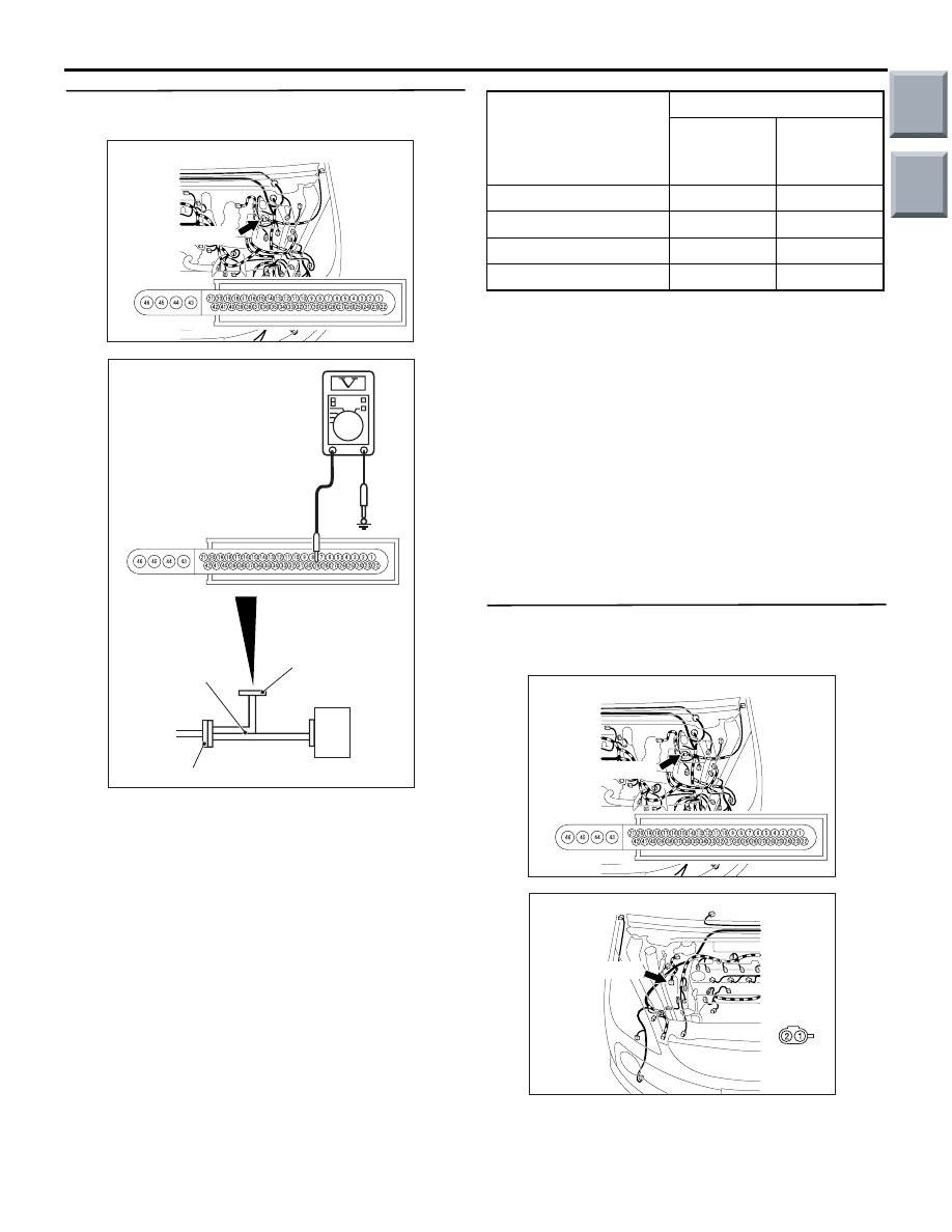
STEP 14. Voltage measurement: A-05 ASC-ECU
connector
(1) Disconnect the connector, connect the ABS
check harness (Special tool: MB991984) to the
ASC-ECU side connector and harness-side
connector, and then measure the voltage at the
special tool connector side.
(2) Ignition switch: ON
(3) Measure the voltage between the power supply
and signal terminals in the wheel speed sensor
circuit and body earth.
OK:
<Power supply terminal> Approximately 12
V
<Signal terminal> 0.4 to 1.3 V
Q: Is the check result normal?
YES :
Go to Step 24.
NO (Not normal at the terminal No. 29 or 28) :
Go
to Step 15.
NO (Not normal at the terminal No. 34 or 13) :
Go
to Step 17.
NO (Not normal at the terminal No. 30 or 8) :
Go to
Step 19.
NO (Not normal at the terminal No. 11 or 10) :
Go
to Step 21.
STEP 15. Connector check: A-05 ASC-ECU
connector, A-29 wheel speed sensor <FR>
connector
Q: Is the check result normal?
YES :
Go to Step 16.
NO :
Repair the damaged connector.
AC601083
Connector: A-05
AB
A-05(Black)
Harness side
AC601086AE
MB991984
ASC-ECU
Check connector
ASC-ECU harness connector
Diagnosis code No.
Checking terminal
Power
supply
terminal
Signal
terminal
C1200
No. 29
No. 28
C1205
No. 34
No. 13
C1210
No. 30
No. 8
C1215
No. 11
No. 10
AC601083
Connector: A-05
AB
A-05(Black)
Harness side
AC601084
Connector: A-29
AB
Harness
side
A-29(black)
Main
Index
Group
TOC

TROUBLESHOOTING
ACTIVE STABILITY CONTROL SYSTEM (ASC)
35C-16
STEP 16. Wiring harness inspection: between
A-05 ASC-ECU connector terminal No. 29, 28 and
A-29 wheel speed sensor <FR> connector
terminal No. 2, 1.
Check for open circuit in wheel speed sensor <FR>
circuit.
Q: Is the check result normal?
YES :
Go to Step 23.
NO :
Repair the wiring harness.
STEP 17. Connector check: A-05 ASC-ECU
connector, A-06 wheel speed sensor <FL>
connector
Q: Is the check result normal?
YES :
Go to Step 18.
NO :
Repair the damaged connector.
STEP 18. Check the harness wire between A-05
ASC-ECU connector terminal No. 34, 13 and A-06
wheel speed sensor <FL> connector terminal No.
2, 1.
Check for open circuit in wheel speed sensor <FL>
circuit.
Q: Is the check result normal?
YES :
Go to Step 23.
NO :
Repair the wiring harness.
AC601083
Connector: A-05
AB
A-05(Black)
Harness side
AC601084
Connector: A-29
AB
Harness
side
A-29(black)
AC601083
Connectors: A-05, A-06
AC
A-05(Black)
A-05:
Harness side
A-06: Harness side
A-06 (Black)
AC601083
Connectors: A-05, A-06
AC
A-05(Black)
A-05:
Harness side
A-06: Harness side
A-06 (Black)
Main
Index
Group
TOC
Нет комментариевНе стесняйтесь поделиться с нами вашим ценным мнением.
Текст