Mitsubishi Colt Ralliart. Manual — part 319

DIAGNOSIS TROUBLE CODE PROCEDURES
SMART WIRING SYSTEM (SWS) NOT USING SWS MONITOR
54B-20
Diagnosis code No.U1701: Communication error with column switch
CAUTION
If diagnosis code No.U1701 is set in the
ETACS-ECU, diagnose the CAN bus lines.
FUSIBLE
LINK
1
IGNITION
SWITCH (IG1)
COLUMN
SWITCH
COLUMN-ECU
ETACS-ECU
DIAGNOSIS
CONNECTOR
FRONT SIDE
Column Switch Power Supply and SWS Communication Circuit
Wire colour code
B : Black LG : Light green G : Green L : Blue W : White Y : Yellow SB : Sky blue
BR : Brown O : Orange GR : Grey R : Red P : Pink V : Violet PU : Purple
Main
Index
Group
TOC

DIAGNOSIS TROUBLE CODE PROCEDURES
SMART WIRING SYSTEM (SWS) NOT USING SWS MONITOR
54B-21
TROUBLE JUDGMENT
The ETACS-ECU communicates with the column
switch through the SWS communication lines. If
there is any trouble in that communication, diagnosis
code No.U1702 will be set.
COMMENT ON TROUBLE SYMPTOM
The column switch, the ETACS-ECU, connector(s),
or wiring harness between the two may be defective.
POSSIBLE CAUSES
• Malfunction of the column switch
• Malfunction of the ETACS-ECU
• Damaged harness wires and connectors
DIAGNOSIS PROCEDURE
Step 1. M.U.T.-III CAN bus diagnostics
Use the M.U.T.-III to diagnose the CAN bus lines.
Q: Is the check result normal?
YES :
Go to Step 2.
NO :
Repair the CAN bus line (Refer to GROUP
54D
− Diagnosis
Step 2. Use the M.U.T.-III to confirm a diagnosis
code. (M.U.T.-III diagnosis code)
(1) Ignition switch: ON
(2) On completion, check that diagnosis code
No.U1701 is not reset.
Q: Is diagnosis code No.U1701 set?
YES :
Go to Step 3.
NO :
The trouble can be an intermittent
malfunction (Refer to GROUP 00
− How to
use Troubleshooting/inspection Service
Points
− How to Cope with Intermittent
).
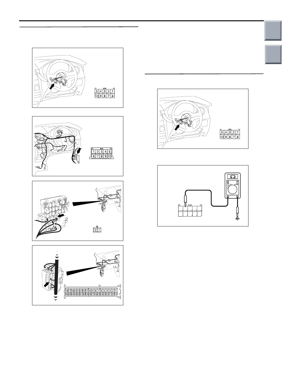
Step 3. Connector check: B-135 column switch
connector
Q: Is the check result normal?
YES :
Go to Step 4.
NO :
Repair the defective connector.
Step 4. Voltage measurement at the B-135
column switch connector.
(1) Disconnect the connector, and measure at the
wiring harness side.
(2) Voltage between B-135 column switch connector
No.1 and body earth
OK: System voltage
Q: Is the check result normal?
YES :
Go to Step 6.
NO :
Go to Step 5.
AC401044AC
Connector: B-135
Harness side
AC401044AC
Connector: B-135
Harness side
AC310507FB
Connector B-135
(Harness side)
Main
Index
Group
TOC
DIAGNOSIS TROUBLE CODE PROCEDURES
SMART WIRING SYSTEM (SWS) NOT USING SWS MONITOR
54B-22
Step 5. Check the wiring harness between B-135
column switch connector terminal No.1 to fusible
link (1).
NOTE:
Prior to the wiring harness inspection, check junction
block connectors B-108, B-131 and joint connector
B-22, and repair if necessary.
• Check the power supply line for open circuit.
Q: Is the check result normal?
YES :
The trouble can be an intermittent
malfunction (Refer to GROUP 00
− How to
use Troubleshooting/inspection Service
Points
− How to Cope with Intermittent
).
NO :
Repair the wiring harness.
Step 6. Resistance measurement at the B-135
column switch connector.
(1) Disconnect the connector, and measure at the
wiring harness side.
(2) Continuity between B-135 column switch
connector No.4 and body earth
OK: Continuity exists (2
Ω or less)
Q: Is the check result normal?
YES :
Go to Step 9.
NO :
Go to Step 7.
AC401044AC
Connector: B-135
Harness side
AC401055
Connector: B-22
AD
AC313870
Connector: B-108
BD
Junction block (Front view)
B-108(B)
Harness side
AC313872
Connector: B-131
BD
Harness side
AC401044AC
Connector: B-135
Harness side
AC310506 DX
Connector B-135
(Harness side)
10
5
6
7
9 8
3
4
2 1
Main
Index
Group
TOC
DIAGNOSIS TROUBLE CODE PROCEDURES
SMART WIRING SYSTEM (SWS) NOT USING SWS MONITOR
54B-23
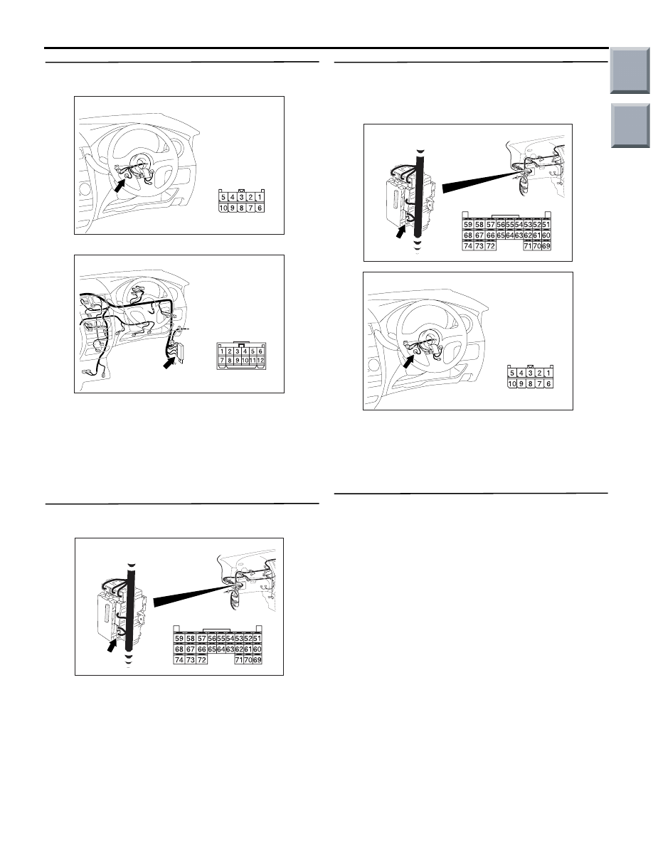
Step 7. Check the wiring harness between B-135
column switch connector No.4 to body earth.
NOTE:
Prior to the wiring harness inspection, check joint
connector B-25, and repair if necessary.
• Check the earth wires for open circuit.
Q: Is the check result normal?
YES :
Go to Step 10.
NO :
Repair the wiring harness.
Step 8. Connector check: B-133 ETACS-ECU
connector
Q: Is the check result normal?
YES :
Go to Step 9.
NO :
Repair the defective connector.
Step 9. Check the wiring harness from B-133
ETACS-ECU connector terminal Nos. 54, 60 and
63 to B-135 column switch connector terminal
Nos. 3, 10 and 2.
• Check the communication lines for open circuit.
Q: Is the check result normal?
YES :
Go to Step 10.
NO :
Repair the wiring harness.
Step 10. Check whether the diagnosis code is
reset.
Replace the column switch, and then check that the
diagnosis code is not reset.
(1) Replace the column switch.
(2) Ignition switch: ON
(3) On completion, check that diagnosis code
No.U1701 is not reset.
Q: Is diagnosis code No.U1701 set?
YES :
Replace the ETACS-ECU.
NO :
The procedure is complete.
AC401044AC
Connector: B-135
Harness side
AC401055
Connector: B-25
AG
AC313826AC
B-133 (GR)
Connector: B-133
Harness side
Junction block (Rear view)
AC313826AC
B-133 (GR)
Connector: B-133
Harness side
Junction block (Rear view)
AC401044AC
Connector: B-135
Harness side
Main
Index
Group
TOC
Нет комментариевНе стесняйтесь поделиться с нами вашим ценным мнением.
Текст