Mitsubishi Colt Ralliart. Manual — part 708

TROUBLESHOOTING
MULTIPORT FUEL INJECTION (MPI) <4G1>
13B-157
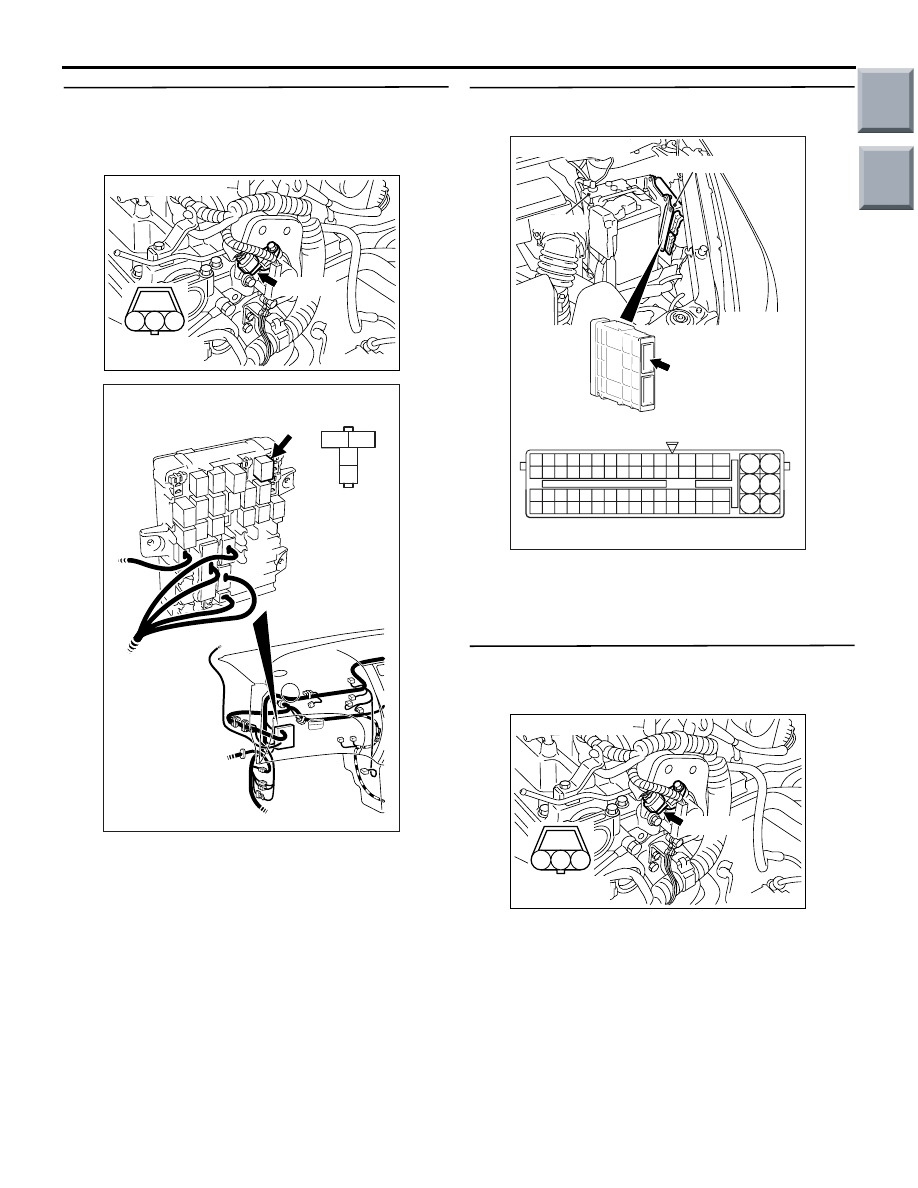
STEP 13. Perform output waveform check at
A-110 camshaft position sensor connector (using
an oscilloscope).
• Use the special tool test harness (MB991709) to
connect the connector, and measure at the
pick-up harness.
• Engine: Idling
• Transmission: Neutral
• Voltage between terminal No. 2 and earth.
OK: Waveforms should be displayed on
Inspection procedure using an oscilloscope
(Refer to
), its maximum value
should be 4.8 V or more, and its minimum
valve should be 0.6 V or less with no noise in
waveform.
Q: Is the check result normal?
YES :
Go to Step 9.
NO :
Go to Step 14.
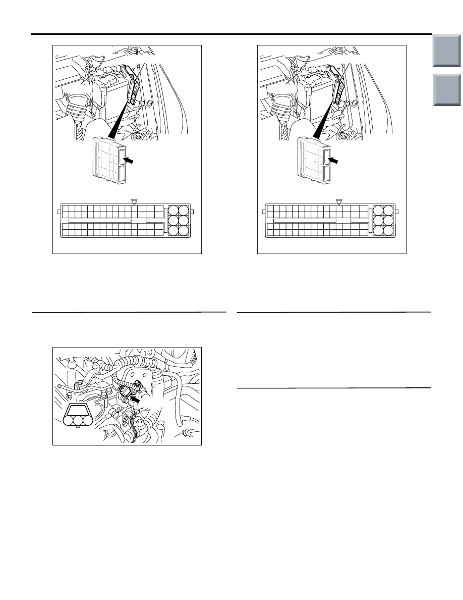
STEP 14. Connector check: B-106 engine control
relay connector
Q: Is the check result normal?
YES :
Go to Step 15.
NO :
Repair or replace.
AK402097
1
2
3
AC
Connector: A-110
Harness side
connector
A-110(B)
3
2
1
4
AK402084
J/B side
connector
B-106
Connector: B-106
J/B (front side)
AC
Main
Index
Group
TOC
TROUBLESHOOTING
MULTIPORT FUEL INJECTION (MPI) <4G1>
13B-158
STEP 15. Check harness between A-110 (terminal
No. 3) camshaft position sensor connector and
B-106 (terminal No. 4) engine control relay
connector.
• Check power supply line for damage.
Q: Is the check result normal?
YES :
Go to Step 16.
NO :
Repair.
STEP 16. Connector check: A-114 engine-ECU
connector
Q: Is the check result normal?
YES :
Go to Step 17.
NO :
Repair or replace.
STEP 17. Check harness between A-110 (terminal
No. 2) camshaft position sensor connector and
A-114 (terminal No. 12) engine-ECU connector.
AK402097
1
2
3
AC
Connector: A-110
Harness side
connector
A-110(B)
3
2
1
4
AK402084
J/B side
connector
B-106
Connector: B-106
J/B (front side)
AC
AK402745
6
4
2
5
3
1
9
7
8
10
11
12
13
14
15
16
17
18
19
20
21
22
23
24
25
26
27
28
29
30
31
32
33
34
35
36
37
38
39
40
41
42
43
44
45
46
47
48
49
50
51
52
53
54
55
56
57
58
59
60
61
62
63
64
65
66
L
AF
A-114
Connector:
A-114
Harness side connector
Engine-ECU
Battery
AK402097
1
2
3
AC
Connector: A-110
Harness side
connector
A-110(B)
Main
Index
Group
TOC
TROUBLESHOOTING
MULTIPORT FUEL INJECTION (MPI) <4G1>
13B-159
• Check output line for damage.
Q: Is the check result normal?
YES :
Go to Step 18.
NO :
Repair.
STEP 18. Check harness between A-110 (terminal
No. 1) camshaft position sensor connector and
A-114 (terminal No. 27) engine-ECU connector.
• Check earthing line for damage.
Q: Is the check result normal?
YES :
Go to Step 19.
NO :
Repair.
STEP 19. Check camshaft position sensing
cylinder.
Q: Is the check result normal?
YES :
Go to Step 20.
NO :
Replace the camshaft position sensing
cylinder.
STEP 20. M.U.T.-III diagnosis code
• Reconfirmation of diagnosis code.
Q: Is the diagnosis code output?
YES :
Replace camshaft position sensor.
NO :
Intermittent malfunction (Refer to GROUP
00
− How to Use
Troubleshooting/Inspection Service Points
−
How to Cope with Intermittent Malfunctions
).
AK402745
6
4
2
5
3
1
9
7
8
10
11
12
13
14
15
16
17
18
19
20
21
22
23
24
25
26
27
28
29
30
31
32
33
34
35
36
37
38
39
40
41
42
43
44
45
46
47
48
49
50
51
52
53
54
55
56
57
58
59
60
61
62
63
64
65
66
L
AF
A-114
Connector:
A-114
Harness side connector
Engine-ECU
Battery
AK402097
1
2
3
AC
Connector: A-110
Harness side
connector
A-110(B)
AK402745
6
4
2
5
3
1
9
7
8
10
11
12
13
14
15
16
17
18
19
20
21
22
23
24
25
26
27
28
29
30
31
32
33
34
35
36
37
38
39
40
41
42
43
44
45
46
47
48
49
50
51
52
53
54
55
56
57
58
59
60
61
62
63
64
65
66
L
AF
A-114
Connector:
A-114
Harness side connector
Engine-ECU
Battery
Main
Index
Group
TOC

TROUBLESHOOTING
MULTIPORT FUEL INJECTION (MPI) <4G1>
13B-160
Code No. P0421: Warm Up Catalyst Malfunction
FUNCTION
• The signal from the oxygen sensor (rear) differs
from the oxygen sensor (front). That is because
the catalytic converter purifies exhaust gas.
When the catalytic converter has deteriorated,
the signal from the oxygen sensor (front)
becomes similar to the oxygen sensor (rear).
• The engine-ECU compares the output of the front
and rear oxygen sensor signals.
TROUBLE JUDGMENT
Check Conditions
• The accelerator pedal is depressed.
• Engine speed is 3,000 r/min or lower.
• Air flow sensor output is 6 g/s or higher.
• 3 seconds or more elapsed after the abovemen-
tioned conditions were satisfied.
• Within the range of air-fuel ratio feed back opera-
tion
• Short-term fuel trim is more than -25% and is less
than 15%
• Vehicle speed is 1.5 km/h or higher.
• For 10 seconds per cycle, the engine-ECU moni-
tors 7 cycles of this condition during the drive
cycle.
• The cumulative air flow sensor output is more
than a prescribed value.
Judgement Criterion
• The oxygen sensor (rear) signal frequency
divided by oxygen sensor (front) signal frequency
is 0.8 or more.
PROBABLE CAUSE
• Catalytic converter deteriorated
• Failed oxygen sensor (front)
• Failed oxygen sensor (rear)
• Failed engine-ECU
DIAGNOSIS PROCEDURE
STEP 1. Check for leakage of exhaust emission
from exhaust manifold.
Q: Is the check result normal?
YES :
Go to Step 2 .
NO :
Repair.
STEP 2. M.U.T.-II/III data list
• Refer to data list reference table
a. Item 11: Oxygen sensor (front)
b. Item 59: Oxygen sensor (rear)
Q: Is the check result normal?
YES :
Go to Step 3 .
NO :
Perform the diagnosis code classified check
procedure for the sensor that has shown an
abnormal data valve (Refer to Inspection
Chart for diagnosis codes
STEP 3. M.U.T.-II/III data list
• Refer to data list reference table
a. Item 11: Oxygen sensor (front)
OK: 0
− 0.4 and 0.6 − 1.0 volt should alternate
15 times or more within 10 seconds (engine
speed at 2,000 r/min).
Q: Is the check result normal?
YES :
Go to Step 4 .
NO :
Replace the oxygen sensor (front).
STEP 4. Replace the oxygen sensor (rear).
• After replacing the oxygen sensor (rear),
re-check the trouble symptoms.
Q: Is the check result normal?
YES :
Go to Step 5 .
NO :
Check end.
STEP 5. Replace the catalytic converter.
• After replacing the catalytic converter, re-check
the trouble symptoms.
Q: Is the check result normal?
YES :
Replacing engine-ECU.
NO :
Check end.
Main
Index
Group
TOC
Нет комментариевНе стесняйтесь поделиться с нами вашим ценным мнением.
Текст