Mitsubishi Colt Ralliart. Manual — part 623

TROUBLESHOOTING
ACTIVE STABILITY CONTROL SYSTEM (ASC)
35C-37
STEP 6. Wheel speed detection magnetic
encoder check
Check the wheel speed detection magnetic encoder
for adhesion of foreign materials or deformation.
NOTE: For the rear wheel speed detection magnetic
encoder, check from the mounting hole of the wheel
speed sensor by rotating the rear hub.
Q: Is the check result normal?
YES :
Go to Step 7.
NO <when the relevant wheel is front> :
When a
foreign material adheres to the encoder,
clean it. When the encoder is deformed,
replace the wheel bearing. (Refer to
GROUP 26
− Front Axle Hub
.)
NO <when the relevant wheel is rear> :
When a
foreign material adheres to the encoder,
clean it. When the encoder is deformed,
replace the rear hub assembly. (Refer to
GROUP 27A
− Rear Axle Hub
.)
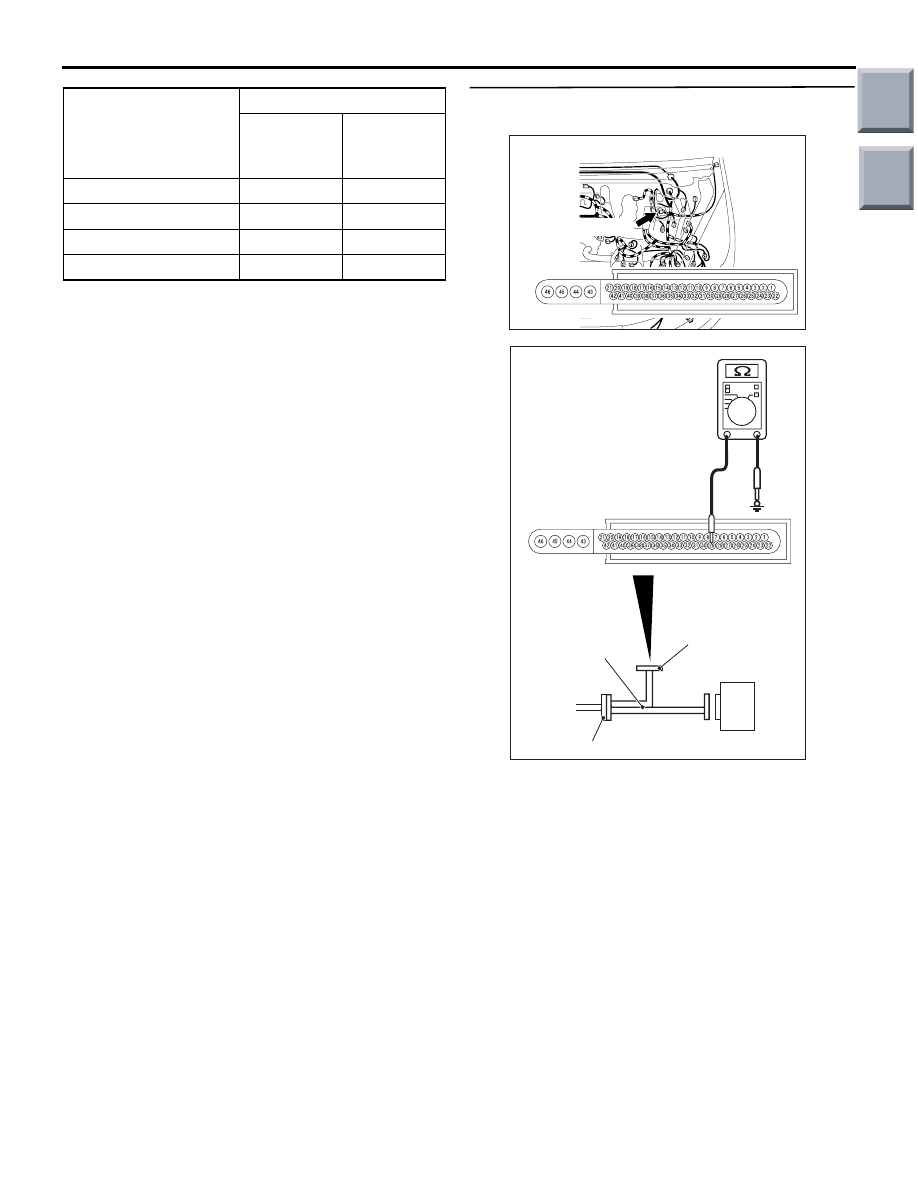
STEP 7. Voltage measurement: A-05 ASC-ECU
connector
(1) Disconnect the connector, connect the ABS
check harness (Special tool: MB991984) to the
harness-side connector, and measure the voltage
at the special tool connector side.
NOTE: Do not connect the special tool to
ASC-ECU.
(2) Ignition switch: ON
(3) Measure the voltage between the power supply
and signal terminals in the wheel speed sensor
circuit and body earth.
AC600965
<Front>
<Rear>
Encoder
AB
Encoder
AC601083
Connector: A-05
AB
A-05(Black)
Harness side
AC601085AB
MB991984
Check connector
ASC-ECU
ASC-ECU harness connector
Main
Index
Group
TOC
TROUBLESHOOTING
ACTIVE STABILITY CONTROL SYSTEM (ASC)
35C-38
OK: 0 V
Q: Is the check result normal?
YES :
Go to Step 8.
NO (Not normal at the terminal No. 29 or 28) :
Go
to Step 9.
NO (Not normal at the terminal No. 34 or 13) :
Go
to Step 10.
NO (Not normal at the terminal No. 30 or 8) :
Go to
Step 11.
NO (Not normal at the terminal No. 11 or 10) :
Go
to Step 12.
STEP 8. Measure the resistance at A-05 ASC-ECU
connector.
(1) Disconnect the connector, connect the ABS
check harness (Special tool: MB991984) to the
harness-side connector, and measure the voltage
at the special tool connector side.
NOTE: Do not connect the special tool to
ASC-ECU.
(2) Measure the resistance between the power
supply and signal terminals in the wheel speed
sensor circuit and body earth.
Wheel speed sensor
position
Checking terminal
Power
supply
terminal
Signal
terminal
Right front wheel
No. 29
No. 28
Left front wheel
No. 34
No. 13
Right rear wheel
No. 30
No. 8
Left rear wheel
No. 11
No. 10
AC601083
Connector: A-05
AB
A-05(Black)
Harness side
AC601085AC
MB991984
ASC-ECU
Check connector
ASC-ECU harness connector
Main
Index
Group
TOC
TROUBLESHOOTING
ACTIVE STABILITY CONTROL SYSTEM (ASC)
35C-39
OK: No continuity
Q: Is the check result normal?
YES :
Go to Step 13.
NO (Not normal at the terminal No. 29 or 28) :
Go
to Step 9.
NO (Not normal at the terminal No. 34 or 13) :
Go
to Step 10.
NO (Not normal at the terminal No. 30 or 8) :
Go to
Step 11.
NO (Not normal at the terminal No. 11 or 10) :
Go
to Step 12.
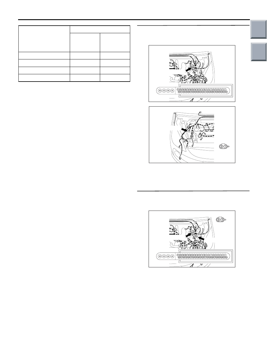
STEP 9. Connector check: A-05 ASC-ECU
connector, A-29 wheel speed sensor <FR>
connector
Q: Is the check result normal?
YES :
Go to Step 15.
NO :
Repair the damaged connector.
STEP 10. Connector check: A-05 ASC-ECU
connector, A-06 wheel speed sensor <FL>
connector
Q: Is the check result normal?
YES :
Go to Step 17.
NO :
Repair the damaged connector.
Wheel speed sensor
position
Checking terminal
Power
supply
terminal
Signal
terminal
Right front wheel
No. 29
No. 28
Left front wheel
No. 34
No. 13
Right rear wheel
No. 30
No. 8
Left rear wheel
No. 11
No. 10
AC601083
Connector: A-05
AB
A-05(Black)
Harness side
AC601084
Connector: A-29
AB
Harness
side
A-29(black)
AC601083
Connectors: A-05, A-06
AC
A-05(Black)
A-05:
Harness side
A-06: Harness side
A-06 (Black)
Main
Index
Group
TOC

TROUBLESHOOTING
ACTIVE STABILITY CONTROL SYSTEM (ASC)
35C-40
STEP 11. Connector check: A-05 ASC-ECU
connector, B-41 intermediate connector, C-06
wheel speed sensor <RR> connector
Q: Is the check result normal?
YES :
Go to Step 19.
NO :
Repair the damaged connector.
STEP 12. Connector check: A-05 ASC-ECU
connector, B-41 intermediate connector, C-17
wheel speed sensor <RL> connector
Q: Is the check result normal?
YES :
Go to Step 21.
NO :
Repair the damaged connector.
AC601083
Connector: A-05
AB
A-05(Black)
Harness side
AC601092
Connector: B-41
AB
AC601093
Connector: C-06
AB
Harness side
C-06 (Black)
AC601083
Connector: A-05
AB
A-05(Black)
Harness side
AC601092
Connector: B-41
AB
AC601094
Connector: C-17
AB
C-17(Black)
Harness side
Main
Index
Group
TOC
Нет комментариевНе стесняйтесь поделиться с нами вашим ценным мнением.
Текст