Mitsubishi Colt Ralliart. Manual — part 117
16-2
IGNITION SYSTEM . . . . . . . . . .
GENERAL INFORMATION . . . . . .
SERVICE SPECIFICATIONS. . . . .
SEALANT <4A9>. . . . . . . . . . . . . .
ON-VEHICLE SERVICE. . . . . . . . .
IGNITION COIL (WITH BUILT-IN
POWER TRANSISTOR) CHECK . . . . .
SPARK PLUG CHECK AND
CLEANING. . . . . . . . . . . . . . . . . . . . . . .
CAMSHAFT POSITION SENSOR
CHECK . . . . . . . . . . . . . . . . . . . . . . . . .
CRANK ANGLE SENSOR CHECK . . . .
DETONATION SENSOR CHECK . . . . .
IGNITION COIL. . . . . . . . . . . . . . . .
REMOVAL AND INSTALLATION
<4A9> . . . . . . . . . . . . . . . . . . . . . . . . . . .
REMOVAL AND INSTALLATION
<4G1>. . . . . . . . . . . . . . . . . . . . . . . . . . .
CAMSHAFT POSITION SENSOR .
REMOVAL AND INSTALLATION
<4A9> . . . . . . . . . . . . . . . . . . . . . . . . . . .
REMOVAL AND INSTALLATION
<4G1>. . . . . . . . . . . . . . . . . . . . . . . . . . .
CRANK ANGLE SENSOR . . . . . . .
REMOVAL AND INSTALLATION
<4A9> . . . . . . . . . . . . . . . . . . . . . . . . . . .
REMOVAL AND INSTALLATION
<4G1>. . . . . . . . . . . . . . . . . . . . . . . . . . .
DETONATION SENSOR . . . . . . . .
REMOVAL AND INSTALLATION
<4A9> . . . . . . . . . . . . . . . . . . . . . . . . . . .
REMOVAL AND INSTALLATION
<4G1>. . . . . . . . . . . . . . . . . . . . . . . . . . .
Main
Index
Group
TOC
CHARGING SYSTEM
ENGINE ELECTRICAL
16-3
CHARGING SYSTEM
GENERAL INFORMATION
M1161000100867
The charging system uses the alternator output to
keep the battery charged at a constant level under
various electrical loads.
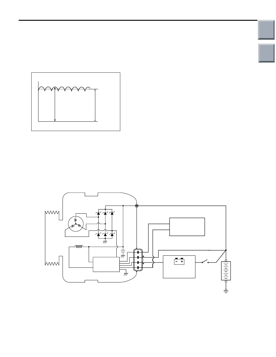
OPERATION
AKX00183
Voltage
Time
Approximately
14.4 V
AC
Rotation of the excited field coil generates AC volt-
age in the stator.
This alternating current is rectified through diodes to
DC voltage having a waveform shown in the illustra-
tion.
The average output voltage fluctuates slightly with
the alternator load condition.
When the ignition switch is turned on, current flows in
the field coil and initial excitation of the field coil
occurs.
When the stator coil begins to generate power after
the engine is started, the field coil is excited by the
output current of the stator coil.
The alternator output voltage rises as the field cur-
rent increases and it falls as the field current
decreases. When the battery voltage (alternator "S"
terminal voltage) reaches a regulated voltage of
approximately 14.4 V, the field current is cut off.
When the battery voltage drops below the regulated
voltage, the voltage regulator regulates the output
voltage to a constant level by controlling the field cur-
rent.
In addition, when the field current is constant, the
alternator output voltage rises as the engine speed
increases.
SYSTEM DIAGRAM
AK503404
Alternator
B
Stator
coil
G
S
L
FR
Voltage
regulator
Ignition
switch
Battery
Field coil
+
–
AB
Charging
warning lamp
Combination
meter
Engine-CVT-ECU
Main
Index
Group
TOC

CHARGING SYSTEM
ENGINE ELECTRICAL
16-4
ALTERNATOR SPECIFICATIONS
Item
Specifications
Type
Battery voltage sensing
Rated output V/A
12/85
Voltage regulator
Electronic built-in type
SERVICE SPECIFICATIONS
M1161000300708
Item
Standard value
Limit
Alternator output line voltage drop (at 30 A) V
−
maximum 0.3
Regulated voltage ambient
temperature at voltage regulator V
−20°C
14.2
− 15.4
−
20
°C
13.9
− 14.9
−
60
°C
13.4
− 14.6
−
80
°C
13.1
− 14.5
−
Output current
−
70 % of normal output current
Field coil resistance
Ω
3
− 5
−
Main
Index
Group
TOC
CHARGING SYSTEM
ENGINE ELECTRICAL
16-5
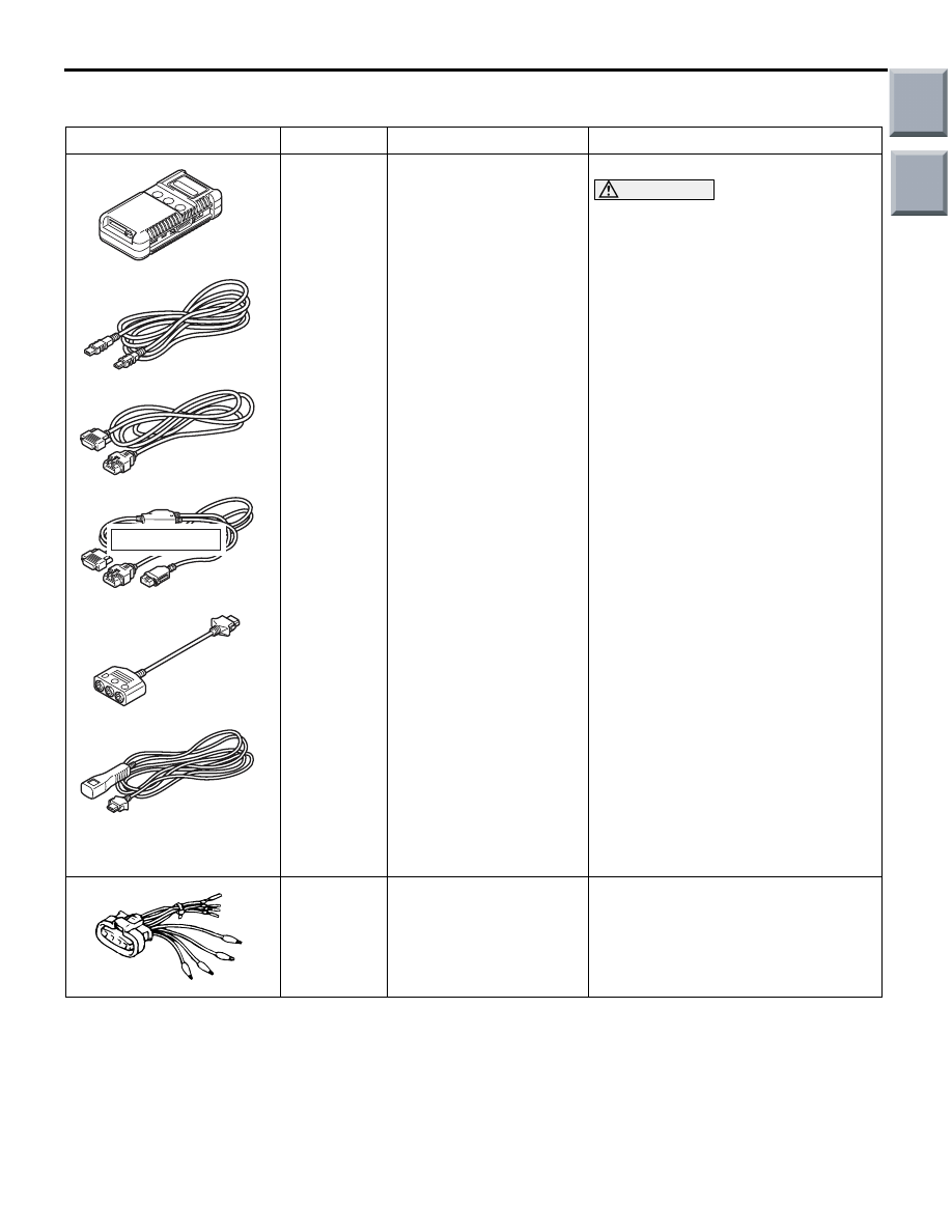
SPECIAL TOOL
M1161000600668
Tool
Number
Name
Use
MB991910
MB991826
MB991955
MB991911
MB991824
MB991827
MB991825
A
B
C
D
E
F
DO NOT USE
MB991955
A:
MB991824
B:
MB991827
C:
MB991910
D:
MB991911
E:
MB991825
F:
MB991826
M.U.T.-III sub assembly
• A: Vehicle
communication
interface (V.C.I.)
• B: M.U.T.-III USB
cable
• C: M.U.T.-III main
harness A (Vehicles
with CAN
communication
system)
• D: M.U.T.-III main
harness B (Vehicles
without CAN
communication
system)
• E: M.U.T.-III
measurement adapter
• F: M.U.T.-III trigger
harness
• Checking the idle speed
For vehicles with CAN
communication, use M.U.T.-III main
harness A to send simulated
vehicle speed. If you connect
M.U.T.-III main harness B instead,
the CAN communication does not
function correctly.
MB991519
Alternator test harness
Checking the alternator
("S" terminal voltage)
CAUTION
Main
Index
Group
TOC
Нет комментариевНе стесняйтесь поделиться с нами вашим ценным мнением.
Текст