Mitsubishi Colt Ralliart. Manual — part 210

STABILIZER BAR
FRONT SUSPENSION
33-17
REMOVAL SERVICE POINTS
<<A>> BOLT (STEERING GEAR AND
STEERING COLUMN ASSEMBLY CON-
NECTION) REMOVAL
AC207740AC
Claw
Clip
Shaft B
Shaft A
Steering column
bolt
1. Remove the steering column bolt securing the
steering gear to the steering column assembly.
2. Disconnect the steering gear from the steering
column assembly while sliding shaft A to shaft B
with the clip claw as shown is pinched.
<<B>>SELF-LOCKING NUT (TIE ROD
END AND KNUCKLE
CONNECTION)/SELF-LOCKING NUT
(LOWER ARM BALL JOINT AND
KNUCKLE CONNECTION) REMOVAL
CAUTION
• The self-locking nut must be only loosened
but not removed from the ball joint. Be sure to
use the special tool.
•
AC208247AL
Cord
Bolt
MB991897 or
MB992011
Self-locking
nut
Ball joint
To prevent the special tool from dropping off,
suspend it with a cord.
1. Install the special tool ball joint remover
(MB991897 or MB992011) as shown in the figure.
AC104739AB
Parallel
Knob
Bolt
Correct
Wrong
2. Turn the bolt and knob to make the special tool
insert horizontal, then hand-tighten the bolt. After
tightening, verify that the insert is still horizontal.
NOTE: When adjusting the special tool wedge
horizontally, position the knob as shown.
3. Turn the bolt to disengage the lower arm ball joint
from the knuckle.
<<C>> FRONT AXLE NO.1
CROSSMEMBER ASSEMBLY REMOVAL
Carry out the works below to gain the clearance
required to remove the stabilizer bar.
AC402971AC
Piece of wood
Transmission
jack
1. Jack up and support the front axle No.1
crossmember assembly with a transmission jack,
and remove the mounting bolts.
2. Lower the front axle No.1 crossmember until the
stabilizer bar can be removed.
>>
C
<<
9.
Steering gear connector (in-vehicle
Electric power steering-ECU side)
>>
B
<<
10. Steering gear bolt (earth bolt)
<<
C
>>
11. Front axle No.1 crossmember
assembly
>>
A
<<
12. Stabilizer bar
Removal steps (Continued)
Main
Index
Group
TOC

STABILIZER BAR
FRONT SUSPENSION
33-18
INSTALLATION SERVICE POINTS
>>A<< STABILIZER BAR/STABILIZER
BUSHING/STABILIZER BAR BRACKET
INSTALLATION
AC405476 AB
Stabilizer bar
bracket (LH)
Outside of
vehicle
Stabilizer
bushing (LH)
Approximately
10 mm
Identification
mark
Align the stabilizer bar identification mark with the
right end of the stabilizer bushing (LH).
>>B<< STEERING GEAR BOLT (EARTH
BOLT) INSTALLATION
AC403448AB
View A
A
0 to 45˚
Tighten the steering gear bolt so that the installation
angle of the earth cable is within the area shown in
the figure.
>>C<< STEERING GEAR CONNECTOR
(IN-VEHICLE EPS-ECU SIDE)
INSTALLATION
AC405880 AB
Electric power steering-ECU
Connector
Grommet
Firmly secure the grommet to the body panel and
connect the connector to the Electric power steer-
ing-ECU.
>>D<< COLLAR/STABILIZER
RUBBER/SELF-LOCKING NUT
INSTALLATION
AC207017
A
AB
Tighten the self-locking nut until its protruding length
meets the standard value (A).
Standard value (A): 19
± 1.5 mm
>>E<< BOLT (STEERING GEAR AND
STEERING COLUMN ASSEMBLY
CONNECTION) INSTALLATION
AC208330 AB
Steering column assembly yoke
Bolt hole
(threaded)
Bolt hole
(non-threaded)
Insert the bolt connecting the steering column
assembly with the steering gear into the
non-threaded bolt hole.
Main
Index
Group
TOC
STABILIZER BAR
FRONT SUSPENSION
33-19
REMOVAL AND INSTALLATION <4G1>
M1332001900440
CAUTION
Before removing the steering wheel and air bag module assembly, refer to GROUP 52B, Service Pre-
cautions
and Air Bag Module and Clock Spring
. Also, put the front wheels in
straight-ahead position. Failure to do so may damage the SRS clock spring and render the SRS air
bag inoperative, which results serious driver injury.
Pre-removal Operation
• Air bag module and steering wheel (Refer to GROUP
52B, Driver’s, front passenger’s air bag module(s) and
).
• Engine room centre under cover
• Engine room side under cover (RH)
• Front exhaust pipe (Refer to GROUP 15, Exhaust pipe
and main muffler
• Engine roll stopper rod assembly (Refer to GROUP 32,
Engine roll stopper rod
).
Post-installation Operation
• Engine roll stopper rod assembly (Refer to GROUP 32,
Engine roll stopper rod
).
• Front exhaust pipe (Refer to GROUP 15, Exhaust pipe
and main muffler
• Engine room side under cover (RH)
• Engine room centre under cover
• Air bag module and steering wheel (Refer to GROUP
52B, Driver’s, front passenger’s air bag module(s) and
).
• Checking steering wheel position with wheels straight
ahead
• Front wheel alignment check and adjustment (Refer to
).
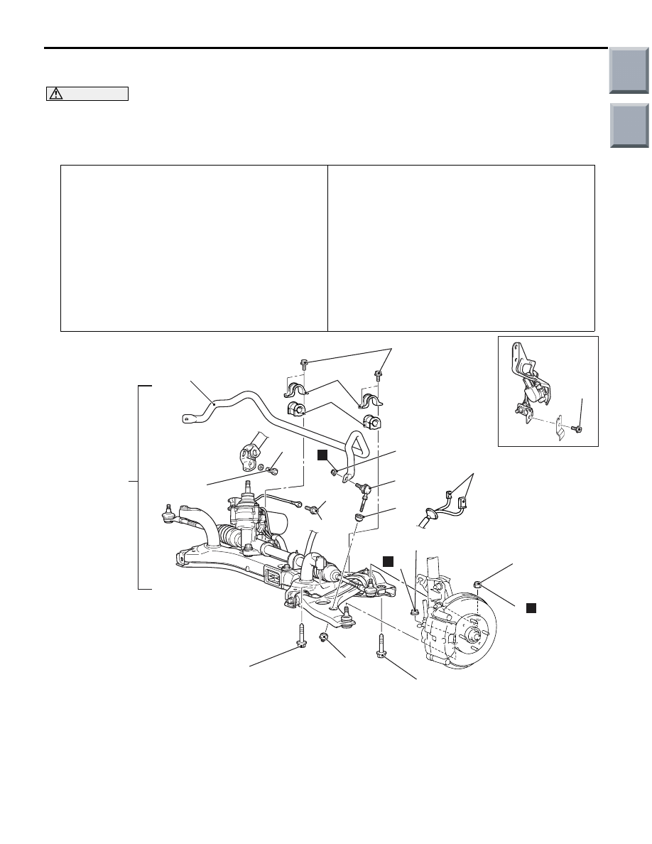
AC601450AC
2
18 ± 2 N·m
8
123 ± 12 N·m
123 ± 12 N·m
28 ± 3 N·m
60 ± 6 N·m
30 ± 5 N·m
39 ± 5 N·m
3
5
6
5
1
N
9
N
13
12
10
9.0 ± 2.0 N·m
11
N
7
Removal steps
<<
A
>>
>>
E
1.
Bolt (Steering gear and steering
column assembly connection)
>>
A
<<
2.
Stabilizer bar bracket
>>
A
<<
3.
Stabilizer bushing
>>
D
<<
4.
Self-locking nut
>>
D
<<
5.
Stabilizer rubber
>>
D
<<
6.
Stabilizer link assembly
7.
Front height sensor and lower arm
connection (LH) <Vehicles with
headlamp auto levelling system>
<<
B
>>
8.
Self-locking nut (lower arm and
knuckle connection)
<<
B
>>
9.
Self-locking nut (Tie rod end and
knuckle connection)
Removal steps (Continued)
Main
Index
Group
TOC

STABILIZER BAR
FRONT SUSPENSION
33-20
REMOVAL SERVICE POINTS
<<A>> BOLT (STEERING GEAR AND
STEERING COLUMN ASSEMBLY CON-
NECTION) REMOVAL
AC207740AC
Claw
Clip
Shaft B
Shaft A
Steering column
bolt
1. Remove the steering column bolt securing the
steering gear to the steering column assembly.
2. Disconnect the steering gear from the steering
column assembly while sliding shaft A to shaft B
with the clip claw as shown is pinched.
<<B>>SELF-LOCKING NUT (TIE ROD
END AND KNUCKLE
CONNECTION)/SELF-LOCKING NUT
(LOWER ARM BALL JOINT AND
KNUCKLE CONNECTION) REMOVAL
CAUTION
• Do not remove the nut from ball joint. Loosen
it and use the special tool to avoid possible
damage to ball joint threads.
•
AC102599AC
Cord
Bolt
MB991113
Nut
Ball joint
Hang the special tool with cord to prevent it
from falling.
Replace the self-locking nut with a regular nut, and
then install special tool steering linkage puller
(MB991113) as shown in the figure.
>>
C
<<
10. Steering gear connector (in-vehicle
Electric power steering-ECU)
>>
B
<<
11. Steering gear bolt (earth bolt)
<<
C
>>
12. Front axle No.1 crossmember
assembly
>>
A
<<
13. Stabilizer bar
Removal steps (Continued)
Main
Index
Group
TOC
Нет комментариевНе стесняйтесь поделиться с нами вашим ценным мнением.
Текст