Mitsubishi Colt Ralliart. Manual — part 174

TROUBLESHOOTING <CVT>
CVT
23A-39
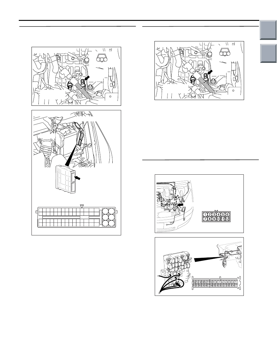
STEP 5. Connector check: A-114
engine-CVT-ECU connector.
AC403088AG
A-114
Connector: A-114
6
4
2
5
3
1
9
7
8
10
11
12
13
14
15
16
17
18
19
20
21
22
23
24
25
26
27
28
29
30
31
32
33
34
35
36
37
38
39
40
41
42
43
44
45
46
47
48
49
50
51
52
53
54
55
56
57
58
59
60
61
62
63
64
65
66
L
A-114 Harness side connector
Engine-CVT-ECU
Battery
(GR)
Check for the contact with terminals.
Q: Is the check result normal?
YES :
Go to Step 6.
NO :
Repair the defective connector.
STEP 6. M.U.T.-III data list
Item 03: Primary speed sensor (Refer to Data List
Table
Q: Is the check result normal?
YES :
Intermittent malfunction (Refer to GROUP
00
− How to Cope with Intermittent
).
NO :
Replace the engine-CVT-ECU.
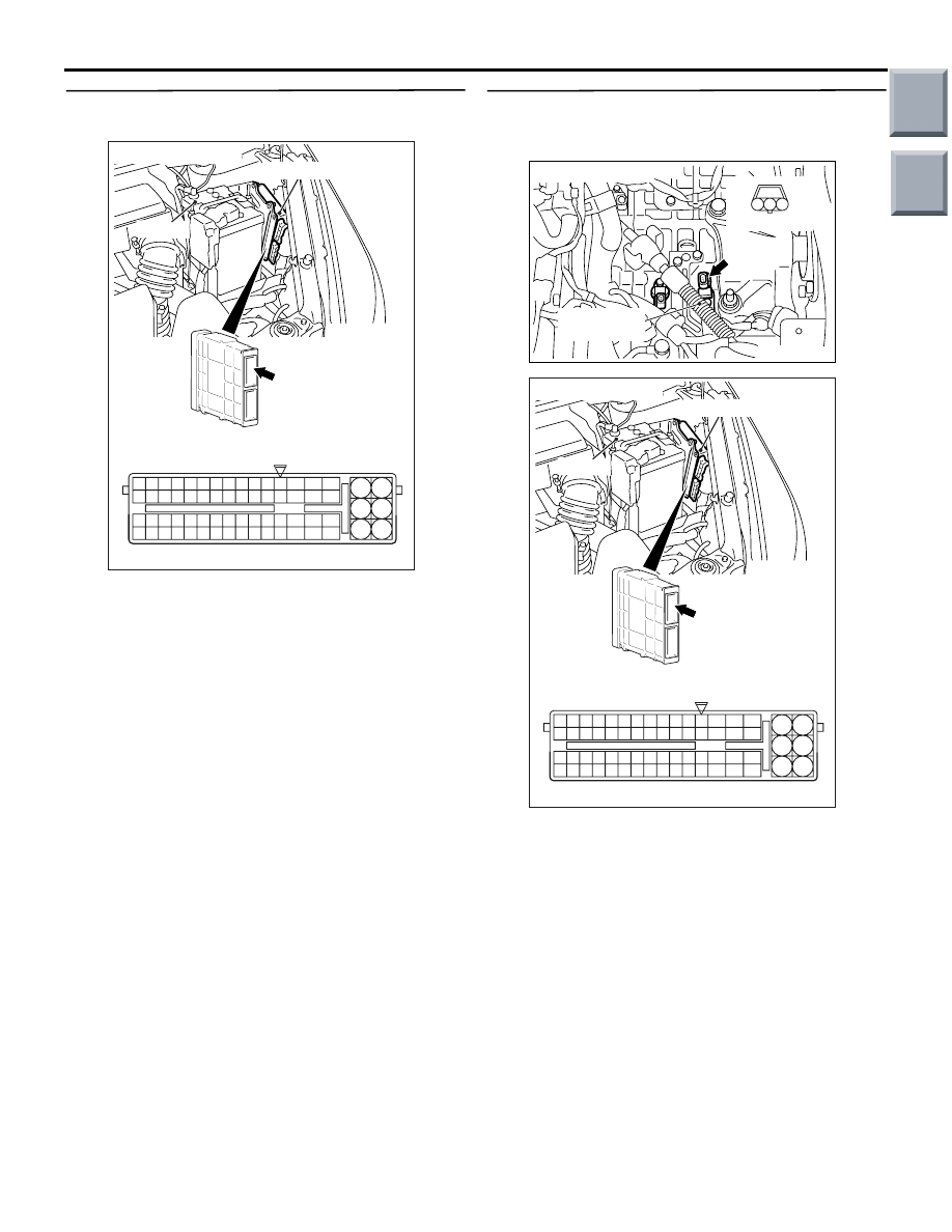
STEP 7. Connector check: A-114
engine-CVT-ECU connector.
AC403088AG
A-114
Connector: A-114
6
4
2
5
3
1
9
7
8
10
11
12
13
14
15
16
17
18
19
20
21
22
23
24
25
26
27
28
29
30
31
32
33
34
35
36
37
38
39
40
41
42
43
44
45
46
47
48
49
50
51
52
53
54
55
56
57
58
59
60
61
62
63
64
65
66
L
A-114 Harness side connector
Engine-CVT-ECU
Battery
(GR)
Check for the contact with terminals.
Q: Is the check result normal?
YES :
Go to Step 8.
NO :
Repair the defective connector.
Main
Index
Group
TOC
TROUBLESHOOTING <CVT>
CVT
23A-40
STEP 8. Check the harness between primary
speed sensor connector A-116 terminal No.1 and
engine-CVT-ECU connector A-114 terminal No.60.
AC314200
Connector: A-116
AC
A-116 (B)
Transmission
control cable
Harness side
1
2
3
AC403088AG
A-114
Connector: A-114
6
4
2
5
3
1
9
7
8
10
11
12
13
14
15
16
17
18
19
20
21
22
23
24
25
26
27
28
29
30
31
32
33
34
35
36
37
38
39
40
41
42
43
44
45
46
47
48
49
50
51
52
53
54
55
56
57
58
59
60
61
62
63
64
65
66
L
A-114 Harness side connector
Engine-CVT-ECU
Battery
(GR)
Check the earth line for open circuit.
Q: Is the check result normal?
YES :
Go to Step 6.
NO :
Repair the wiring harness.
STEP 9. Measure the voltage at primary speed
sensor connector A-116.
AC314200
Connector: A-116
AC
A-116 (B)
Transmission
control cable
Harness side
1
2
3
(1) Disconnect the connector, and measure the
voltage between terminal 3 and earth at the
wiring harness side.
(2) Turn the ignition switch to the ON position.
OK: System voltage
Q: Is the check result normal?
YES :
Go to Step 12.
NO :
Go to Step 10.
STEP 10. Connectors check: A-17 intermediate
connector, B-112 J/B connector.
AC313811 AG
Connector: A-17
A-17 (B)
AC313824 AO
Connector: B-112
Harness side
Junction block (Front view)
Check for the contact with terminals.
Q: Is the check result normal?
YES :
Go to Step 11.
NO :
Repair the defective connector.
Main
Index
Group
TOC

TROUBLESHOOTING <CVT>
CVT
23A-41
STEP 11. Check the harness between primary
speed sensor connector A-116 terminal No.3 and
J/B connector B-112 terminal No.6.
AC314200
Connector: A-116
AC
A-116 (B)
Transmission
control cable
Harness side
1
2
3
AC313824 AO
Connector: B-112
Harness side
Junction block (Front view)
Check the power supply line for short-circuited or
open circuit.
Q: Is the check result normal?
YES :
Go to Step 6.
NO :
Repair the wiring harness.
STEP 12. Measure the voltage at primary speed
sensor connector A-116.
AC314200
Connector: A-116
AC
A-116 (B)
Transmission
control cable
Harness side
1
2
3
(1) Disconnect the connector, and measure the
voltage between terminal 2 and earth at the
wiring harness side.
(2) Turn the ignition switch to the ON position.
OK: 4.9
− 5.1 V
Q: Is the check result normal?
YES : .
Go to Step 18.
NO : .
Go to Step 13.
STEP 13. Measure the voltage at
engine-CVT-ECU connector A-114.
(1) Connect primary speed sensor connector A-116.
AC403088AF
A-114
Connector: A-114
6
4
2
5
3
1
9
7
8
10
11
12
13
14
15
16
17
18
19
20
21
22
23
24
25
26
27
28
29
30
31
32
33
34
35
36
37
38
39
40
41
42
43
44
45
46
47
48
49
50
51
52
53
54
55
56
57
58
59
60
61
62
63
64
65
66
L
A-114 Check connector (special tool)
Engine-CVT-ECU
Battery
(GR)
(2) Disconnect the engine-CVT-ECU connector, and
connect the special tool Power plant ECU check
harness (MB991987).
(3) Turn the ignition switch to the ON position.
(4) Use the special tool Check connector to measure
the voltage between engine-CVT-ECU connector
A-114 terminal No.43 and earth.
OK: 4.9
− 5.1 V
Q: Is the check result normal?
YES :
Go to Step 16.
NO :
Go to Step 14.
Main
Index
Group
TOC
TROUBLESHOOTING <CVT>
CVT
23A-42
STEP 14. Connector check: A-114
engine-CVT-ECU connector.
AC403088AG
A-114
Connector: A-114
6
4
2
5
3
1
9
7
8
10
11
12
13
14
15
16
17
18
19
20
21
22
23
24
25
26
27
28
29
30
31
32
33
34
35
36
37
38
39
40
41
42
43
44
45
46
47
48
49
50
51
52
53
54
55
56
57
58
59
60
61
62
63
64
65
66
L
A-114 Harness side connector
Engine-CVT-ECU
Battery
(GR)
Check for the contact with terminals.
Q: Is the check result normal?
YES :
Go to Step 15.
NO :
Repair the defective connector.
STEP 15. Check the harness between primary
speed sensor connector A-116 terminal No.2 and
engine-CVT-ECU connector A-114 terminal No.43.
AC314200
Connector: A-116
AC
A-116 (B)
Transmission
control cable
Harness side
1
2
3
AC403088AG
A-114
Connector: A-114
6
4
2
5
3
1
9
7
8
10
11
12
13
14
15
16
17
18
19
20
21
22
23
24
25
26
27
28
29
30
31
32
33
34
35
36
37
38
39
40
41
42
43
44
45
46
47
48
49
50
51
52
53
54
55
56
57
58
59
60
61
62
63
64
65
66
L
A-114 Harness side connector
Engine-CVT-ECU
Battery
(GR)
Check the output line for short-circuited.
Q: Is the check result normal?
YES :
Go to Step 6.
NO :
Repair the wiring harness.
Main
Index
Group
TOC
Нет комментариевНе стесняйтесь поделиться с нами вашим ценным мнением.
Текст