Mitsubishi Colt Ralliart. Manual — part 750

TROUBLESHOOTING
MULTIPORT FUEL INJECTION (MPI) <4G1>
13B-325
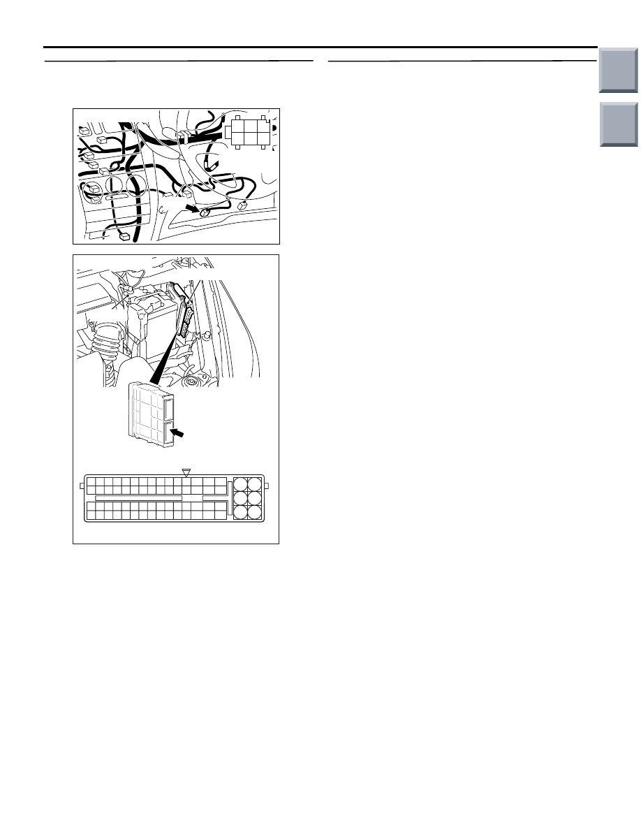
STEP 5. Connector check: A-08 engine-ECU
connector
Q: Is the check result normal?
YES :
Go to Step 6 .
NO :
Repair or replace.
STEP 6. Perform voltage measurement at A-08
engine-ECU connector.
• Disconnect engine-ECU connector, and connect
Special Tool Power Plant ECU Check Harness
(MB991987), and measure the voltage on the
check connector.
• Voltage between terminal No. 128 and earth.
OK:
System voltage (Brake pedal: Depressed)
1 V or less (Brake pedal: Released)
Q: Is the check result normal?
YES :
Go to Step 8 .
NO :
Go to Step 7 .
AK402725
77
78
79
80
81
82
83
84
92
93
94
95
96
97
98
99
85
86
87
88
89
90
91
100
101
102
103
104
105
106
115
116
117
118
119
120
121
107
108
109
110
111
112
113
114
130
131
132
133
134
135
136
122
123
124
125
126
127
128
129
72 71
74 73
76 75
R
AI
A-08
Connector:
A-08
A-08 Special tool power plant ECU check
harness
Engine-ECU
Battery
Main
Index
Group
TOC
TROUBLESHOOTING
MULTIPORT FUEL INJECTION (MPI) <4G1>
13B-326
STEP 7. Check harness between B-59 (terminal
No. 3) stop lamp switch connector and A-08
(terminal No. 128) engine-ECU.
• Check output line for open/short circuit.
Q: Is the check result normal?
YES :
Check and repair the stop lamp switch
output signal harness and connector for
short circuit.
NO :
Repair.
STEP 8. M.U.T.-III data list
• Refer to Data List Reference Table
.
a. Item 67: Stop lamp switch
Q: Is the check result normal?
YES :
Intermittent malfunction (Refer to GROUP
00
− How to Use
Troubleshooting/Inspection Service Points
−
How to Cope with Intermittent Malfunctions
).
NO :
Replace engine-ECU.
AK600593
1
2
3
4
5
6
AB
Connector: B-59
Harness side
connector
B-59
AK402725
77
78
79
80
81
82
83
84
92
93
94
95
96
97
98
99
85
86
87
88
89
90
91
100
101
102
103
104
105
106
115
116
117
118
119
120
121
107
108
109
110
111
112
113
114
130
131
132
133
134
135
136
122
123
124
125
126
127
128
129
72 71
74 73
76 75
R
AI
A-08
Connector:
A-08
A-08 Special tool power plant ECU check
harness
Engine-ECU
Battery
Main
Index
Group
TOC
TROUBLESHOOTING
MULTIPORT FUEL INJECTION (MPI) <4G1>
13B-327
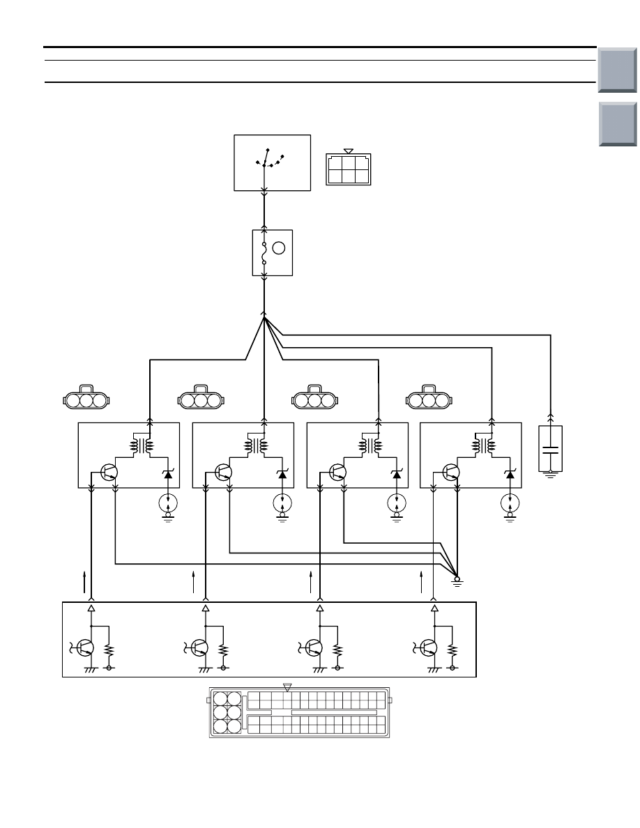
Inspection Procedure 26: Ignition Circuit System
AK402687
39
1 2 3
4 5 6
1
2 3
1
2 3
1
2 3
1
2 3
19
21
20
18
17
16
15
14
1213
11
8 9
L
10
37
52 53 54 555657585960616263646566
38 39 404142434445464748495051
22 23 24 252627282930313233343536
7
5
3
1
6
4
2
Wire colour code
B: Black LG: Light green G: Green L: Blue W: White Y: Yellow SB: Sky blue BR: Brown O: Orange GR: Gray
R: Red P: Pink V: Violet P: Purple
LOCK
ACC
IG1 IG2
ST
10A
Ignition coil 1
Engine-ECU
A-135
(MU802053)
A-127
(MU802053)
A-126
(MU802053)
A-123
(MU802053)
Ignition coil 2
Ignition coil 3
Ignition coil 4
2
3
10
25
40
55
Noise
condenser
A-111
Ignition switch
L-B
B-W
B-W
B-W
B-W
B-W
B-W
W
W-G
W-B
W-L
B
B
B
B
2
3
15
B-112
A-17
3
B-129
J/B
Ignition Circuit
A-114
AE
Spark
plug
2
1
1
1
1
1
3
Spark
plug
2
3
Spark
plug
2
3
Spark
plug
B141
Main
Index
Group
TOC

TROUBLESHOOTING
MULTIPORT FUEL INJECTION (MPI) <4G1>
13B-328
OPERATION
• The battery voltage is applied to the ignition coil
(terminal No. 1) from the ignition switch and is
earthed to the vehicle body from the ignition coil
(terminal No. 2).
• A power voltage of 12 V is applied to the ignition
coil (terminal No. 3) from the engine-ECU (termi-
nals No. 10, No. 25, No. 40 and No. 55).
FUNCTION
• When the engine-ECU makes the power transis-
tor in the unit be in OFF position, the battery volt-
age is applied to the power transistor in the
ignition coil, making the power transistor be in ON
position. The engine-ECU makes the power tran-
sistor in the unit be in ON position, and that
makes the power transistor in the ignition coil be
in OFF position.
• When the power transistor in the ignition coil is
turned to ON position in response to the signal
from the engine-ECU, the primary current flows
through the ignition coil. When the power transis-
tor in the ignition coil is turned to OFF position,
the primary current is interrupted and high volt-
age is generated in the secondary coil.
PROBABLE CAUSES
• Failed spark plug
• Failed ignition coil
• Open/short circuit in or damage to the ignition cir-
cuit or loose connector contact
• Failed engine-ECU
DIAGNOSIS PROCEDURE
STEP 1. Connector check: A-123, A-126, A-127
and A-135 ignition coil connector
Q: Is the check result normal?
YES :
Go to Step 2 .
NO :
Repair or replace.
STEP 2. Check ignition coil.
• Check ignition coil (Refer to GROUP 16 − Ignition
System
− On-vehicle Service − Ignition Coil
Check
).
Q: Is the check result normal?
YES :
Go to Step 3 .
NO :
Replace ignition coil.
STEP 3. Perform voltage measurement at A-123,
A-126, A-127 and A-135 ignition coil connectors.
•
Disconnect connector and measure at harness side.
• Ignition switch: ON
• Voltage between terminal No. 1 and earth.
OK: System voltage
Q: Is the check result normal?
YES :
Go to Step 5 .
NO :
Go to Step 4 .
AK402093
1
2
3
A-123(DG)
A-126(DG)
A-127(DG)
A-135(DG)
AC
Harness side connector
Connector: A-123, A-126, A-127, A-135
AK402093
1
2
3
A-123(DG)
A-126(DG)
A-127(DG)
A-135(DG)
AC
Harness side connector
Connector: A-123, A-126, A-127, A-135
Main
Index
Group
TOC
Нет комментариевНе стесняйтесь поделиться с нами вашим ценным мнением.
Текст