Mitsubishi Colt Ralliart. Manual — part 55

TROUBLESHOOTING
MULTIPORT FUEL INJECTION (MPI) <4A9>
13A-174
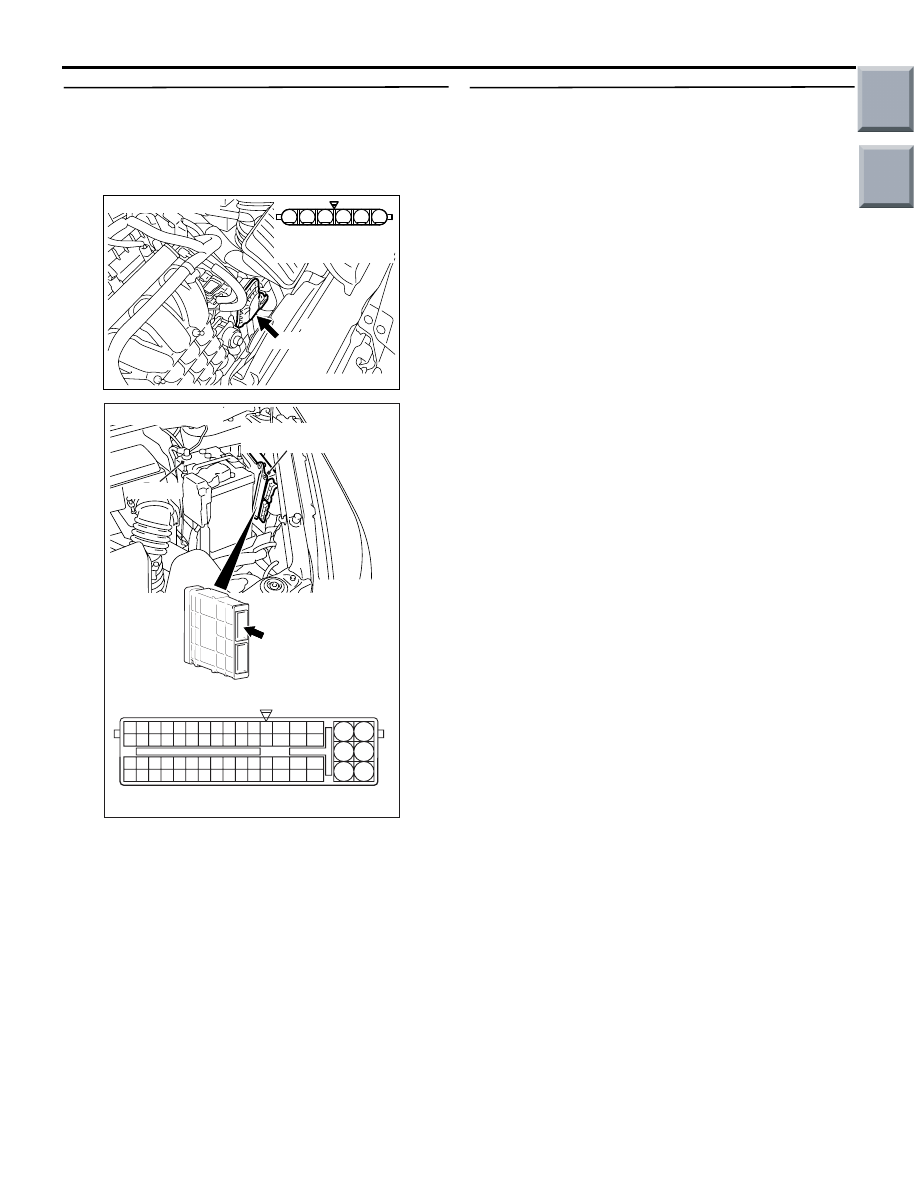
STEP 3. Connector check: A-107
electronic-controlled throttle valve connector
and A-114 engine-ECU connector or
engine-CVT-ECU connector
Q: Is the check result normal?
YES :
Go to Step 4 .
NO :
Repair or replace the connector.
STEP 4. Check harness between A-107 (terminal
No. 1) electronic-controlled throttle valve
connector and A-114 (terminal No. 7) engine-ECU
connector or engine-CVT-ECU connector.
• Check output line for short circuit and damage.
Q: Is the check result normal?
YES :
Go to Step 5 .
NO :
Repair the damaged harness wire.
AK402006
1
6 5 4 3 2
AC
A-107 (B)
Connector: A-107
A-107 Harness side
connector
AK402745
6
4
2
5
3
1
9
7
8
10
11
12
13
14
15
16
17
18
19
20
21
22
23
24
25
26
27
28
29
30
31
32
33
34
35
36
37
38
39
40
41
42
43
44
45
46
47
48
49
50
51
52
53
54
55
56
57
58
59
60
61
62
63
64
65
66
L
AD
A-114
Connector:
A-114
Harness side connector
Engine-ECU <M/T> or
engine-CVT-ECU <CVT>
Battery
Main
Index
Group
TOC
TROUBLESHOOTING
MULTIPORT FUEL INJECTION (MPI) <4A9>
13A-175
STEP 5. Check harness between A-107 (terminal
No. 2) electronic-controlled throttle valve
connector and A-114 (terminal No. 22)
engine-ECU connector or engine-CVT-ECU
connector.
• Check output line for short circuit and damage.
Q: Is the check result normal?
YES :
Go to Step 6 .
NO :
Repair the damaged harness wire.
STEP 6. Check the trouble symptoms.
Q: Does trouble symptom persist?
YES :
Replace engine-ECU <M/T> or
engine-CVT-ECU <CVT>.
NO :
Intermittent malfunction (Refer to GROUP
00
− How to Use
Troubleshooting/Inspection Service Points
−
How to Cope with Intermittent Malfunctions
).
AK402006
1
6 5 4 3 2
AC
A-107 (B)
Connector: A-107
A-107 Harness side
connector
AK402745
6
4
2
5
3
1
9
7
8
10
11
12
13
14
15
16
17
18
19
20
21
22
23
24
25
26
27
28
29
30
31
32
33
34
35
36
37
38
39
40
41
42
43
44
45
46
47
48
49
50
51
52
53
54
55
56
57
58
59
60
61
62
63
64
65
66
L
AD
A-114
Connector:
A-114
Harness side connector
Engine-ECU <M/T> or
engine-CVT-ECU <CVT>
Battery
Main
Index
Group
TOC
TROUBLESHOOTING
MULTIPORT FUEL INJECTION (MPI) <4A9>
13A-176
Code No. P0642: Throttle Position Sensor Power Supply
FUNCTION
• The engine-ECU <M/T> or engine-CVT-ECU
<CVT> checks the throttle position sensor power
voltage for abnormal conditions.
TROUBLE JUDGMENT
Check Conditions
• Ignition switch is in "ON" position <M/T>.
• Battery positive voltage is 6.3 V or higher.
Judgement Criteria
• Throttle position sensor power voltage is 4.1 V or
less <M/T>.
• Throttle position sensor power voltage is 4.1 V or
less for 0.3 seconds <CVT>.
PROBABLE CAUSE
• Failed engine-ECU <M/T> or engine-CVT-ECU
<CVT>
DIAGNOSIS
STEP 1. Check the trouble symptoms.
Q: Does trouble symptom persist?
YES :
Replace engine-ECU <M/T> or
engine-CVT-ECU <CVT>.
NO :
Intermittent malfunction (Refer to GROUP
00
− How to Use
Troubleshooting/Inspection Service Points
−
How to Cope with Intermittent Malfunctions
).
Main
Index
Group
TOC

TROUBLESHOOTING
MULTIPORT FUEL INJECTION (MPI) <4A9>
13A-177
Code No. P0657: Throttle Valve Control Servo Relay Circuit Malfunction
OPERATION
• Battery voltage is applied to the throttle valve
control servo relay terminal (terminal No. 3).
• Battery voltage is applied to the throttle valve
control servo relay terminal (terminal No. 1) from
the engine control relay (terminal No. 4).
• The engine-ECU <M/T> or engine-CVT-ECU
<CVT> (terminal No. 123) applies current to the
throttle valve control servo relay coil by turning
ON the power transistor in the unit in order to turn
the relay ON.
AK503598
3
1
2
4
3
1
2
4
R
92 93 94 95969798
77 78 79 808182838485868788899091
99
100
107 108 109 110 111112113114115116117118119120121
122 123 124 125126127128129130131132133134135136
101102103104105106
71 72
73 74
75 76
AC
Power source
L-W
R-L
Wire colour code
B: Black LG: Light green G: Green L: Blue W: White Y: Yellow SB: Sky blue BR: Brown O: Orange GR: Gray
R: Red P: Pink V: Violet PU: Purple
Engine-ECU <M/T> or
engine-CVT-ECU <CVT>
Throttle Valve Control Servo Relay Circuit
Engine
control
relay
Throttle
valve
control
servo
relay
B-106
B-121
B-108
3
1
4
2
3
1
32
B-112
B-110
5
78
123
4
2
1
1
R
Fusible link
16
20A
J/B
To
engine-ECU <M/T> or
engine-CVT-ECU <CVT>
A-08
Main
Index
Group
TOC
Нет комментариевНе стесняйтесь поделиться с нами вашим ценным мнением.
Текст