Mitsubishi Colt Ralliart. Manual — part 352

SYMPTOM PROCEDURES
SMART WIRING SYSTEM (SWS) NOT USING SWS MONITOR
54B-152
Step 3. Resistance measurement at the E-12 rear
combination lamp (tail: LH) connector or E-03
rear combination lamp (tail: RH) connector, A-12
front combination lamp (position: LH) connector
or A-25 front combination lamp (position: RH)
connector or E-07 licence plate lamp (LH)
connector.
(1) Disconnect the connector, and measure at the
wiring harness side.
(2) Check the resistance between the lamp
connector and body earth.
•
Resistance between A-12 front combination lamp
(position: LH) connector terminal No.6 and
body earth
• Resistance between A-25 front combination
lamp (position: RH) connector terminal No.6
and body earth
•
Resistance between E-12 rear combination lamp
(tail: LH) connector terminal No.5 and body
earth
• Resistance between E-03 rear combination
lamp (tail: RH) connector terminal No.5 and
body earth
•
Resistance between E-07 licence plate lamp con-
nector terminal No.2 and body earth
OK: Continuity exists (2
Ω or less)
Q: Is the check result normal?
YES :
Go to Step 5.
NO :
Go to Step 4.
AC509191
Connector: A-12
Harness side
AB
A-12 (B)
AC509176
Connector: A-25
Harness side
AC
A-25(B)
AC401047
Connectors: E-03, E-07, E-12
Harness side
E-03
AB
E-03(B)
E-07
E-12(B)
Harness side
E-12
Harness side
E-07
AC313972 DJ
Connectors: A-12, A-25
(Harness side)
AC313972 AX
Connectors: E-03, E-12
(Harness side)
AC400966AG
Connector: E-07
(Harness side)
Main
Index
Group
TOC

SYMPTOM PROCEDURES
SMART WIRING SYSTEM (SWS) NOT USING SWS MONITOR
54B-153
Step 4. Check the wiring harness from E-12 rear
combination lamp (tail: LH) connector terminal
No.5 or E-03 rear combination lamp (tail: RH)
connector terminal No.5, A-12 front combination
lamp (position: LH) connector terminal No.6 or
A-25 front combination lamp (position: RH)
connector terminal No.6 or E-07 licence plate
lamp (LH) connector terminal No.2 to body earth.
• Check the earth wires for open circuit.
Q: Is the check result normal?
YES :
Go to Step 5.
NO :
Repair the wiring harness.
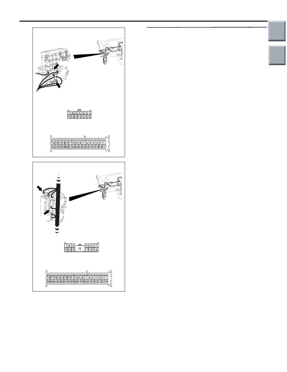
Step 5. Connector check: B-134 ETACS-ECU
connector
Q: Is the check result normal?
YES :
Go to Step 6.
NO :
Repair the defective connector.
AC509191
Connector: A-12
Harness side
AB
A-12 (B)
AC509176
Connector: A-25
Harness side
AC
A-25(B)
AC401047
Connectors: E-03, E-07, E-12
Harness side
E-03
AB
E-03(B)
E-07
E-12(B)
Harness side
E-12
Harness side
E-07
AC313872 AH
Connector: B-134
Harness side
Junction block (Rear view)
Main
Index
Group
TOC

SYMPTOM PROCEDURES
SMART WIRING SYSTEM (SWS) NOT USING SWS MONITOR
54B-154
Step 6. Check the wiring harness from E-12 rear
combination lamp (tail: LH) connector terminal
No.3 or E-03 rear combination lamp (tail: RH)
connector terminal No.3, A-12 front combination
lamp (position: LH) connector terminal No.5 or
A-25 front combination lamp (position: RH)
connector terminal No.5 or E-07 licence plate
lamp (LH) connector terminal No.1 to B-134
ETACS-ECU connector terminal No.15.
NOTE:
AC509191
Connector: A-12
Harness side
AB
A-12 (B)
AC509176
Connector: A-25
Harness side
AC
A-25(B)
AC313872 AH
Connector: B-134
Harness side
Junction block (Rear view)
AC401047
Connectors: E-03, E-07, E-12
Harness side
E-03
AB
E-03(B)
E-07
E-12(B)
Harness side
E-12
Harness side
E-07
AC401056
Connectors: B-23, B-24
AC
B-23
B-24
B-24
B-23
Main
Index
Group
TOC
SYMPTOM PROCEDURES
SMART WIRING SYSTEM (SWS) NOT USING SWS MONITOR
54B-155
Prior to the wiring harness inspection, check junction
block connectors B-128 <tail lamp (LH) or licence
plate lamp>, B-131 <tail lamp (RH)>, B-112 <position
lamp (LH)>, B-110 <position lamp (RH)>, joint con-
nector B-23 and B-24, and repair if necessary.
• Check the output lines for open circuit.
Q: Is the check result normal?
YES :
Go to Step 7.
NO :
Repair the wiring harness.
Step 7. Retest the system.
Check that the tail/stop lamps, the position lamps
and the licence plate lamps illuminate normally.
Q: Is the check result normal?
The lamps illuminate normally at both high and low
beams. :
The trouble can be an intermittent
malfunction (Refer to GROUP 00
− How to
use Troubleshooting/inspection Service
Points
− How to Cope with Intermittent
).
When the tail lamps do not illuminate :
Replace
the tail lamp socket.
When the position lamps do not illuminate :
Replace the position lamp socket.
When the licence plate lamps do not illuminate :
Replace the licence plate lamp socket.
AC313871
Connectors: B-110, B-112
BD
Junction block (Front view)
Harness side
B-110
B-110
Harness side
B-112
B-112
AC313873
Connectors: B-128, B-131
BC
Junction block (Front view)
B-128
B-131
Harness side
B-131
Harness side
B-128
Main
Index
Group
TOC
Нет комментариевНе стесняйтесь поделиться с нами вашим ценным мнением.
Текст