Mitsubishi Colt Ralliart. Manual — part 516
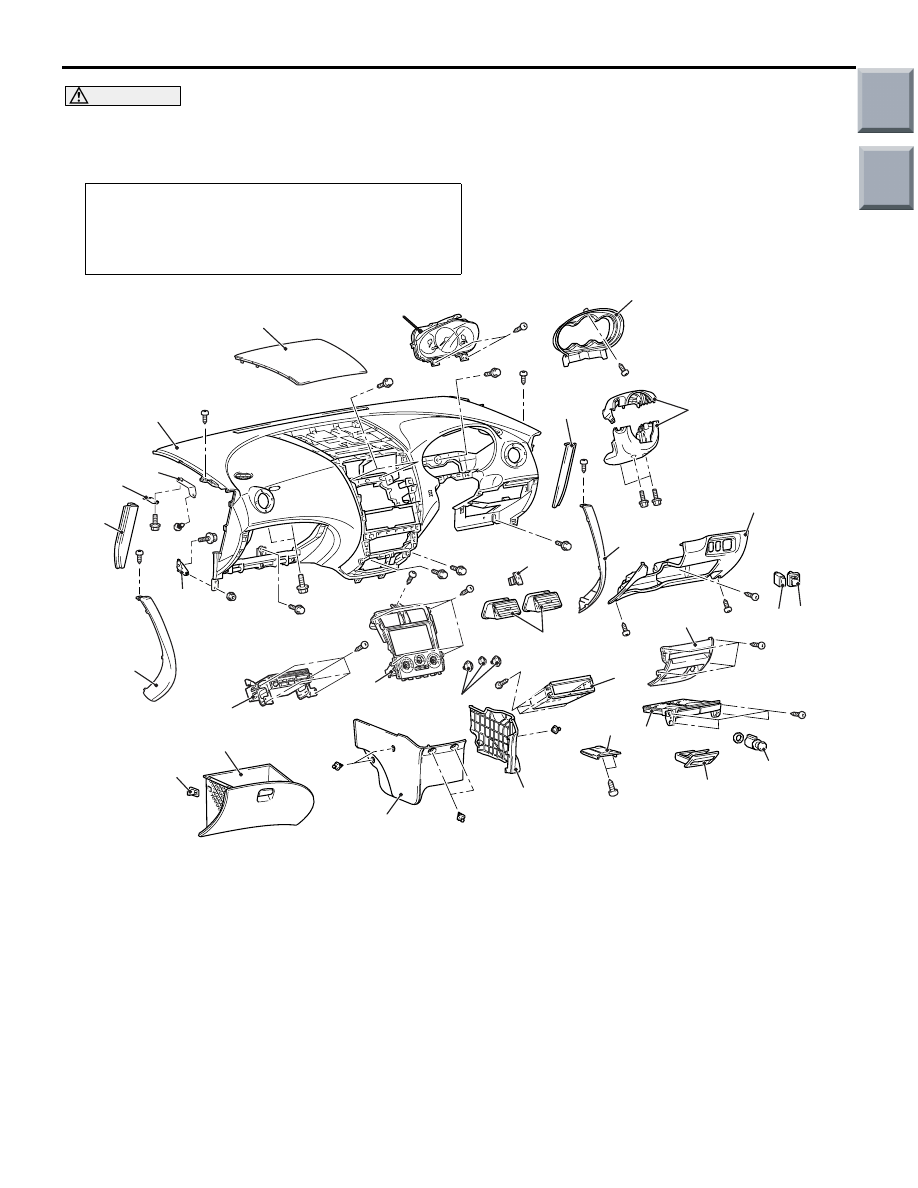
INSTRUMENT PANEL ASSEMBLY
INTERIOR
52A-4
CAUTION
• Refer to GROUP 52B, SRS Service Precautions
and Driver’s, Front Passenger’s Air bag
Module(s) and Clock Spring
before removing the passenger side air bag module.
•
Pre-removal and Post-installation Operation
• Removal and Installation of Front Pillar Trim (Refer to
• Removal and Installation of Hood Lock Release Handle
(Refer to GROUP 42, Hood
).
AC400406
2
3
1
23
8
4
5 6
10
19
13
12
11
9
20
16
14
20
15
22
21
18
8
23
24
7
AB
17
e
j
l
l
e
l
l
l
l
e
g
j
c c
e
e
a
e
f
f
f
e
e
m
27
26
25
l
e
k
Do not subject the SRS-ECU to any shocks when removing or installing the instrument panel.
Removal steps
1.
Steering column cover
<<
A
>>
2.
Combination meter bezel
3.
Combination meter assembly
4.
Lower panel
5.
Fog lamp switch <Vehicles with fog
lamp>
6.
Remote control mirror switch
•
Steering wheel (refer to GROUP
37, Steering Wheel
•
Air bag module (refer to GROUP
52B, Driver’s, Front Passenger’s
Air Bag Module(s) and Clock Spring
•
Steering shaft (refer to GROUP 37,
Steering Shaft
7.
Upper centre panel
8.
Console panel
9.
Ashtray
10. Lower centre panel
11. Cigarette lighter
12. Ashtray cover
13. Parcel box bracket
14. Air control knob
15. Heater control panel
16. Hazard lamp switch
17. Air outlet
18. Radio assembly
Removal steps (Continued)
Main
Index
Group
TOC
INSTRUMENT PANEL ASSEMBLY
INTERIOR
52A-5
19. Box
20. Centre console
21. Glove box stopper
22. Glove box assembly
23. Side cover
•
Clock spring connector
•
Column switch connector
•
Ignition key reminder switch
connector
•
Ignition switch connector
•
Air bag module (squib) (front
passenger’s side) connector
24. Instrument panel assembly
25. Front cowl side bracket
26. Glove box striker A
27. Glove box striker B
Removal steps (Continued)
Main
Index
Group
TOC

INSTRUMENT PANEL ASSEMBLY
INTERIOR
52A-6
CLIP AND CRAW POSITIONS
AC208419AB
A
A
B
B
C
C
D
D
B
B
A
A
H
I
I
J
J
E
E
E
E
F
F
G
G
Claw
Side cover
Instrument panel
Claw
Side cover
Instrument
panel
Instrument panel
Upper centre panel
Clip
Instrument panel
Upper centre panel
Clip
Combination meter
bezel
Instrument panel
Console panel
Clip
Instrument panel
Claw
Console panel
Instrument panel
Claw
Steering column cover
Claw
Clip
Lower panel
Instrument panel
Claw
H
Console panel
Clip
Instrument panel
NOTE
(1) : Clip positions
(2) : Claw positions
Section A – A
Section B – B
Section C – C
Section D – D
Section E – E
Section F – F
Section G – G
Section H – H
Section I – I
Section J – J
Main
Index
Group
TOC

INSTRUMENT PANEL ASSEMBLY
INTERIOR
52A-7
REMOVAL SERVICE POINTS
<<A>> COMBINATION METER BEZEL
REMOVAL
AC209041
Flat-tipped
screwdriver
Clip
Steering shaft
AE
Unclip the combination meter bezel with a flat-tipped
screwdriver as shown, and remove the combination
meter bezel.
Main
Index
Group
TOC
Нет комментариевНе стесняйтесь поделиться с нами вашим ценным мнением.
Текст