Mitsubishi Colt Ralliart. Manual — part 417

SYMPTOM PROCEDURES
SMART WIRING SYSTEM (SWS) USING SWS MONITOR
54C-176
COMMENTS ON TROUBLE SYMPTOM
If any of the turn-signal lamp does not illuminate nor-
mally, wiring harness connector(s) or the bulb may
be defective.
POSSIBLE CAUSES
• Defective front turn-signal lamp bulb
• Defective head lamp assembly
• Defective side turn-signal lamp
• Defective rear turn-signal lamp bulb
• Damaged harness wires and connectors
DIAGNOSIS PROCEDURE
Step 1. Confirm which turn-signal lamp is
defective.
Q: Which turn-signal lamp fails to illuminate
correctly?
Front turn-signal lamp :
Go to Step 2.
Side turn-signal lamp :
Go to Step 8.
Rear turn-signal lamp :
Go to Step 14.
ETACS-ECU
REAR
COMBINATION
LAMP
(TURN: LH)
FRONT
COMBINATION
LAMP
(TURN: LH)
SIDE TURN-
SIGNAL
LAMP
(LH)
J/B SIDE
Turn-Signal Lamps Circuit (LH)
Wire colour code
B : Black LG : Light green G : Green L : Blue W : White Y : Yellow SB : Sky blue
BR : Brown O : Orange GR : Grey R : Red P : Pink V : Violet PU : Purple
Main
Index
Group
TOC
SYMPTOM PROCEDURES
SMART WIRING SYSTEM (SWS) USING SWS MONITOR
54C-177
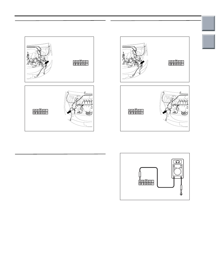
Step 2. Connector check: A-25 <front
combination lamp (turn: RH)> or A-12 <front
combination lamp (turn: LH)> connector
Q: Are the check results normal?
YES :
Go to Step 3.
NO :
Repair the defective connector.
Step 3. Check the bulb(s) of the turn-signal
lamps.
Check the bulb(s) of the defective lamp.
Q: Is the check result normal?
YES :
Go to Step 4.
NO :
Replace the bulb(s) of the defective lamp.
Step 4. Resistance measurement at A-25 <front
combination lamp (turn: RH)> or A-12 <front
combination lamp (turn: LH)> connector
(1) Disconnect the connector, and measure at the
wiring harness side.
(2) Measure the resistance between the defective
lamp connector terminal and body earth.
•
Resistance between A-25 <front combination
lamp (turn: RH)> connector or A-12 <front
combination lamp (turn: LH)> connector ter-
minal No.6 and body earth
OK: Continuity exists (2
Ω or less)
Q: Is the check result normal?
YES :
Go to Step 6.
NO :
Go to Step 5.
AC509191
Connector: A-12
Harness side
AB
A-12 (B)
AC509176
Connector: A-25
Harness side
AC
A-25(B)
AC509191
Connector: A-12
Harness side
AB
A-12 (B)
AC509176
Connector: A-25
Harness side
AC
A-25(B)
AC313972 DJ
Connectors: A-12, A-25
(Harness side)
Main
Index
Group
TOC
SYMPTOM PROCEDURES
SMART WIRING SYSTEM (SWS) USING SWS MONITOR
54C-178
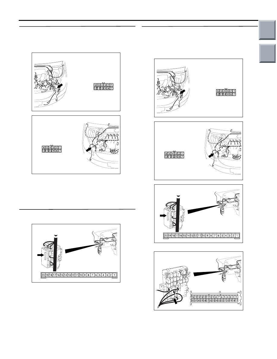
Step 5. Check the wiring harness from A-25
<front combination lamp (turn: RH)> or A-12
<front combination lamp (turn: LH)> connector
terminal No.6 and body earth.
• Check the earth wires for open circuit.
Q: Is the check result normal?
YES :
Go to Step 6.
NO :
Repair the wiring harness.
Step 6. Connector check: B-134 ETACS-ECU
connector
Q: Is the check result normal?
YES :
Go to Step 7.
NO :
Repair the defective connector.
Step 7. Check the wiring harness from A-25
<front combination lamp (turn: RH)> connector
or A-12 <front combination lamp (turn: LH)>
connector terminal No.12 and B-134 ETACS-ECU
connector terminal No.4 (RH) or No.3 (LH).
NOTE:
Prior to the wiring harness inspection, check junction
block connector B-112, and repair if necessary.
• Check the output lines for open circuit.
AC509191
Connector: A-12
Harness side
AB
A-12 (B)
AC509176
Connector: A-25
Harness side
AC
A-25(B)
AC313826
Connector: B-134
AG
Junction block side
Junction block (Rear view)
AC509191
Connector: A-12
Harness side
AB
A-12 (B)
AC509176
Connector: A-25
Harness side
AC
A-25(B)
AC313826
Connector: B-134
AG
Junction block side
Junction block (Rear view)
AC313870
Connector: B-112
BE
Junction block (Front view)
Harness side
Main
Index
Group
TOC

SYMPTOM PROCEDURES
SMART WIRING SYSTEM (SWS) USING SWS MONITOR
54C-179
Q: Is the check result normal?
YES :
Go to Step 20.
NO :
Repair the wiring harness.
Step 8. Connector check: A-01 <side turn-signal
lamp (RH)> or A-07 <side turn-signal lamp (LH)>
connector
Q: Are the check results normal?
YES :
Go to Step 9.
NO :
Repair the defective connector.
Step 9. Check the bulb(s) of the turn-signal
lamps.
Check the bulb(s) of the defective lamp.
Q: Is the check result normal?
YES :
Go to Step 10.
NO :
Replace the bulb(s) of the defective lamp.
Step 10. Resistance measurement at A-01 <side
turn-signal lamp (RH)> or A-07 <side turn-signal
lamp (LH)> connector
(1) Disconnect the connector, and measure at the
wiring harness side.
(2) Measure the resistance between the defective
lamp connector terminal and body earth.
•
Resistance between A-01 <side turn-signal lamp
(RH)> connector or A-07 <side turn-signal
lamp (RH)> connector terminal No.1 and
body earth
OK: Continuity exists (2
Ω or less)
Q: Is the check result normal?
YES :
Go to Step 12.
NO :
Go to Step 11.
AC313797AE
A-01 (GR)
Connector: A-01
Harness side
AC313811AJ
A-07 (GR)
Connector: A-07
Harness side
AC313797AE
A-01 (GR)
Connector: A-01
Harness side
AC313811AJ
A-07 (GR)
Connector: A-07
Harness side
AC310506 ED
Connectors A-01, A-07
(Harness side)
Main
Index
Group
TOC
Нет комментариевНе стесняйтесь поделиться с нами вашим ценным мнением.
Текст