Mitsubishi Colt Ralliart. Manual — part 267

CAMSHAFT
ENGINE OVERHAUL <4A9>
11B-32
INSPECTION
M1113027000091
CAMSHAFT
AK304883
Measure the cam height. If the measured value
exceeds the limit, replace the camshaft.
Standard value:
Intake: 44.71 mm
Exhaust: 44.28 mm
Limit:
Intake: 44.21 mm
Exhaust: 43.78 mm
VALVE TAPPET
AK304938
AB
Wall
thickness
1. Measure the valve tappet at the illustrated
location. If the measured valve is discord to
instruction valve by identification mark and
following table, replace the tappet.
AK305693
Identification mark
AB
2. Every valve tappet has an identification mark
stamped at the illustrated location.
Valve tappets are available in 31 sizes, at 0.02
mm intervals in the 2.70
− 3.30 mm range, as
shown in the following table.
Thickness mm ID mark
Thickness mm ID mark
Thickness mm ID mark
2.70
70
2.92
92
3.14
14
2.72
72
2.94
94
3.16
16
2.74
74
2.96
96
3.18
18
2.76
76
2.98
98
3.20
20
2.78
78
3.00
00
3.22
22
2.80
80
3.02
02
3.24
24
2.82
82
3.04
04
3.26
26
2.84
84
3.06
06
3.28
28
2.86
86
3.08
08
3.30
30
2.88
88
3.10
10
2.90
90
3.12
12
Main
Index
Group
TOC

CYLINDER HEAD AND VALVES
ENGINE OVERHAUL <4A9>
11B-33
CYLINDER HEAD AND VALVES
REMOVAL AND INSTALLATION
M1113006900992
AK402342
AC
7
10
11
8
1
6
5
4
3
9
24.5 ± 2 N·m
→ +180˚ to 184˚
21
19
20
17
18
16
15
14
13
12
2
Apply engine oil to
all moving parts
before installation.
Removal steps
>>
C
<< 1. Cylinder head bolt
2. Cylinder head bolt washer
3. Cylinder head assembly
4. Cylinder head gasket
<<
A
>> >>
B
<< 5. Retainer lock
6. Valve spring retainer
7. Valve spring
8. Intake valve
<<
A
>> >>
B
<< 9. Retainer lock
10.Valve spring retainer
11. Valve spring
12.Exhaust valve
>>
A
<< 13.Valve stem seal
14.Valve spring seat
>>
A
<< 15.Valve stem seal
16.Valve spring seat
17.Valve guide
18.Valve guide
19.Intake valve seat
20.Exhaust valve seat
21.Cylinder head
Removal steps (Continued)
Main
Index
Group
TOC

CYLINDER HEAD AND VALVES
ENGINE OVERHAUL <4A9>
11B-34
REMOVAL SERVICE POINTS
<<A>> RETAINER LOCK REMOVAL
AK304941AB
MD999597
While compressing the valve spring using the special
tool Valve spring compressor (MD999597), remove
the retainer lock.
NOTE: To facilitate reassembly, the valve, spring and
other parts removed should be kept together and
attached with a tag showing where it has been
assembled including the cylinder number.
INSTALLATION SERVICE POINTS
>>A<< VALVE STEM SEAL INSTALLA-
TION
AK304886AB
MB991994
Valve
stem
seal
1. Install the valve spring seat.
CAUTION
• The valve stem seal should not be reused.
• A new valve stem seal should be installed
correctly using the special tool. Incorrectly
installed valve stem seal will allow engine oil
to leak through into the combustion chamber.
2. Lightly coat a new valve stem seal with engine oil.
3. Insert the new valve stem seal into the valve
guide using the special tool Valve stem seal
installer (MB991994).
NOTE: . Use the special tool, on which the
number "MB991994A" is stamped.
>>B<< RETAINER LOCK INSTALLATION
AK304941AB
MD999597
While compressing the valve spring using the special
tool Valve spring compressor (MD999597), install the
retainer lock.
>>C<< CYLINDER HEAD BOLT
INSTALLATION
AK401051
15 mm
29 mm
40 mm
A
B
AB
1. Inspect all reused cylinder bolts according to the
following procedure.
(1) Measure the outside diameter shown in the
illustration (arrow "A").
(2) Measure the smaller outside diameter shown
in the illustration (arrow "B").
(3) When the difference between the smaller
outside diameters (arrow "A" and "B") exceeds
the standard value, replace the cylinder head
bolt.
Standard value: 0
− 0.15 mm
2. Install the cylinder head bolt and washer
assembly onto the cylinder head.
Main
Index
Group
TOC
AK305406AB
Timing chain side
6
3
4
7
8
9
2
1
5
10
CYLINDER HEAD AND VALVES
ENGINE OVERHAUL <4A9>
11B-35
3. In accordance with the installation order, tighten
them to the specified torque of 24.5
± 2 N⋅m in
several steps.
4. Make sure all bolts reach the specified torque.
AK304945
Paint mark
Paint mark
AB
180
˚
to 184
˚
5. Put paint marks on the bolt heads and the cylinder
as illustrated.
CAUTION
• If the head bolt is tightened less than the
specified lower limit of 180 degree angle, the
bolt may become loose. Be sure to tighten
correctly.
• If the head bolt is tightened in excess of the
specified upper limit of 184 degree angle,
loosen the bolt completely and repeat the
entire procedures.
6. Tighten the bolts in the correct sequence by 180
to 184 degree angle.
Ensure that the paint marks on the bolt heads and
the cylinder are aligned in a straight line.
INSPECTION
M1113007000862
CYLINDER HEAD
1. Before cleaning, check the cylinder head for
leakage of coolant or exhaust gas as well as
cracks or other damage.
2. Remove oil, scale, sealant, carbon and other
residues completely. Clean the oil passages and
blow compressed air through them to verify that
they are free of restriction.
AK304943
CAUTION
The grinding limit for the cylinder head and block
combined is 0.2 mm.
3. Using a straight edge and a thickness gauge,
measure the flatness of the cylinder head bottom
surface. If the distortion exceeds the limit, correct
it by grinding.
Bottom face distortion
Standard value: 0.03 mmor less
Limit: 0.2 mm
Grinding limit: 0.2 mm
Cylinder head height (standard value for new
part): 113.0 mm
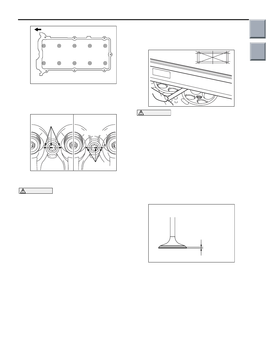
VALVE
AK305408AB
Margin
The bottom of valve
seat contact facet
1. If the valve face-to-seat contact is uneven or
interrupted, correct the valve seat.
2. Measure the valve head margin. If the measured
value exceeds the limit, replace with a new valve.
Standard value:
Intake 1.35 mm
Exhaust 1.85 mm
Limit:
Intake 0.85 mm
Exhaust 1.35 mm
Main
Index
Group
TOC
Нет комментариевНе стесняйтесь поделиться с нами вашим ценным мнением.
Текст