Mitsubishi Colt Ralliart. Manual — part 458

POWER STEERING GEAR BOX AND LINKAGE
POWER STEERING
37-99
<<B>> STEERING GEAR AND STEERING
COLUMN ASSEMBLY DISCONNECTION
AC207740 AB
Clip
Steering column
bolt
Claw
Shaft B
Shaft A
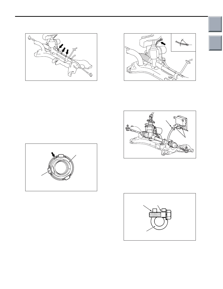
1. Remove the steering column bolt connecting
steering gear to steering column assembly.
2. Disconnect the steering gear from the steering
column assembly while sliding shaft A to shaft B
with the clip claw as shown is pinched.
<<C>> FRONT AXLE NO.1
CROSSMEMBER (EQUIPPED WITH
STEERING GEAR AND LINKAGE
ASSEMBLY, STEERING COLUMN DASH
PANEL COVER, STABILIZER BAR)
REMOVAL
AC208331AB
Clip
Steering column
dash panel cover
1. Remove the 3 clips (shown in the figure) from
inside of the vehicle and drop the steering column
dash panel cover through the body panel.
2. Remove the front axle No.1 crossmember.
INSTALLATION SERVICE POINTS
>>A<< STEERING GEAR CUSHION
INSTALLATION
AC207427 AB
Steering gear cushion
251 mm
Apply the specified adhesive to the steering gear
cushion and install it to the steering gear and linkage
assembly as shown.
Instant adhesive: ThreeBond 1741 or equiva-
lent
>>B<< STEERING COLUMN DASH PANEL
COVER INSTALLATION
AC208332AB
Steering gear
Steering column
dash panel cover
Notch
Projection
Install the steering column dash panel cover so that
the cover notch is aligned with the projection of the
steering gear and linkage assembly.
Main
Index
Group
TOC
POWER STEERING GEAR BOX AND LINKAGE
POWER STEERING
37-100
>>C<< STEERING GEAR AND LINKAGE
ASSEMBLY INSTALLATION
AC314191AB
Harness clip
After installing the steering gear and linkage assem-
bly to the front axle No.1 crossmember, secure the 3
harness clips of the steering gear and linkage
assembly to the front axle No.1 crossmember.
>>D<< FRONT AXLE NO.1
CROSSMEMBER (EQUIPPED WITH
STEERING GEAR AND LINKAGE
ASSEMBLY, STEERING COLUMN DASH
PANEL COVER, STABILIZER BAR)
INSTALLATION
AC208331AC
Clip
Steering column
dash panel cover
Tab
After installing the front axle No.1 crossmember to
the body, pull the steering column dash panel cover
tab (shown in the figure) from inside of the vehicle
and secure the 3 clips to the body panel.
>>E<< STEERING GEAR BOLT (EARTH
BOLT) INSTALLATION
AC403448AB
View A
A
0 to 45˚
Tighten the steering gear bolt so that the earth cable
is routed as shown.
>>F<< STEERING GEAR CONNECTOR
(IN-VEHICLE EPS-ECU) INSTALLATION
AC405880 AB
Electric power steering-ECU
Connector
Grommet
Firmly secure the grommet to the body panel and
connect the connector to the electric power steer-
ing-ECU.
>>G<< STEERING GEAR AND STEERING
COLUMN ASSEMBLY CONNECTION
AC208330 AB
Steering column assembly yoke
Bolt hole
(threaded)
Bolt hole
(non-threaded)
Insert the steering column bolt into the non-threaded
bolt hole.
Main
Index
Group
TOC
POWER STEERING GEAR BOX AND LINKAGE
POWER STEERING
37-101
INSPECTION
M1372011000367
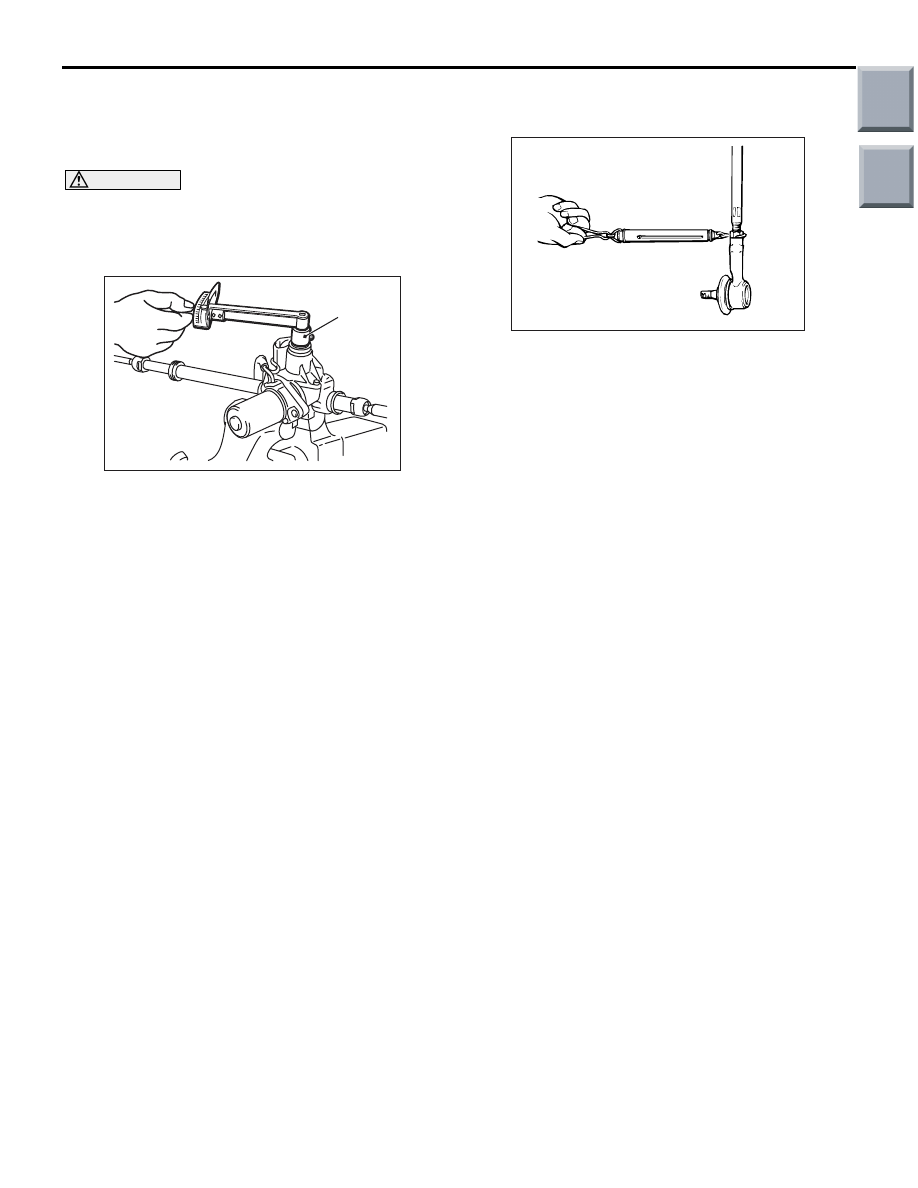
STEERING GEAR TOTAL PINION
TORQUE CHECK
CAUTION
When holding the steering gear in a vice, secure
its mounting positions. If it is secured in any
other place, the gear housing may become
deformed or damaged.
AC208337AB
MB991006
1. Using special tool preload socket (MB991006),
rotate the pinion gear at the rate of one rotation in
approximately 4 to 6 seconds to check the total
pinion torque.
Standard value:
TOTAL PINION TORQUE: 1.29
− 2.23 N⋅m
Change in torque: 0.92 N
⋅m or less
NOTE: When measuring, remove the bellows
from the rack housing. Measure the pinion torque
through the whole stroke of the rack.
2. If not within the specification, replace the steering
gear and linkage assembly (Refer to
).
TIE ROD SWING RESISTANCE CHECK
1. Give 10 hard swings to the tie rod.
AC000997
2. Measure the tie rod swing resistance [tie rod
swing torque] with a spring balance.
Standard value: 6
− 19 N [1.5 − 4.9 N⋅m]
3. If the measured value exceeds the standard
value, replace the tie rod.
4. If the measured value is below the standard value,
the tie rod can be re-used if it swings smoothly
without excessive play.
TIE ROD END BALL JOINT DUST COVER
CHECK
1. Check the dust cover for cracks or damage by
pushing it with your finger.
2. If the dust cover is cracked or damaged, replace
the tie rod end (Refer to
).
NOTE: Cracks or damage of the dust cover may
damage the ball joint. If it is damaged during serv-
ice work, replace the dust cover (Refer to
Main
Index
Group
TOC

ELECTRIC POWER STEERING CONTROL UNIT
POWER STEERING
37-102
ELECTRIC POWER STEERING CONTROL UNIT
REMOVAL AND INSTALLATION
M1372006300049
Pre-removal and post-installation Operation
Front Scuff Plate, Cowl Side Trim Removal and
Installation (Refer to GROUP 52A, Trim
− Interior
AC207737AC
1
13 ± 2 N·m
2
3
4
5.0 ± 1.0 N·m
3
13 ± 2 N·m
3
Removal steps
1.
Electric power steering-ECU
bracket
2.
Electric power steering-ECU
connector (4 pieces)
3.
Electric power steering-ECU
equipment nut (one of three nuts is
an earth nut).
4.
Electric power steering-ECU
Removal steps (Continued)
Main
Index
Group
TOC
Нет комментариевНе стесняйтесь поделиться с нами вашим ценным мнением.
Текст