Mitsubishi Colt Ralliart. Manual — part 276

VEHICLE IDENTIFICATION
GENERAL
00-17
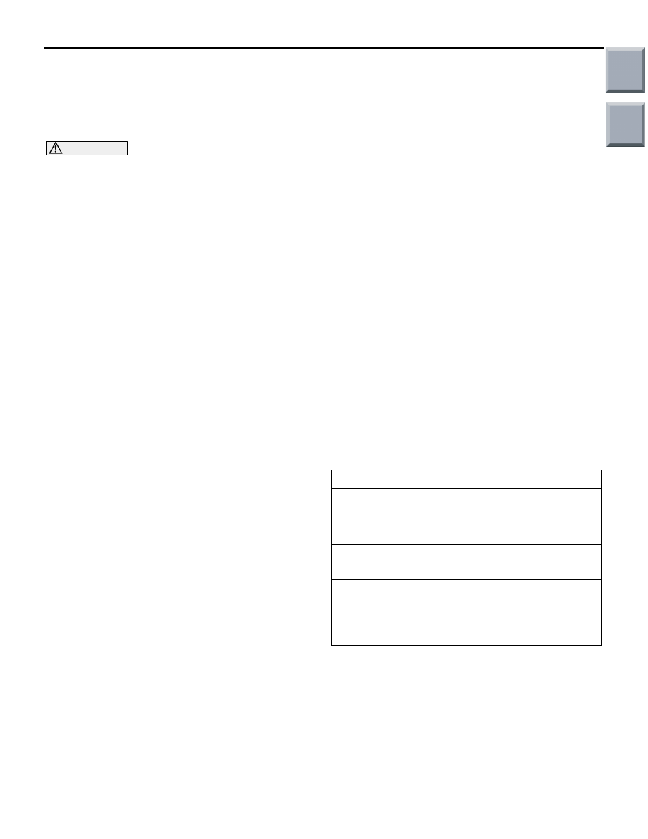
ENGINE MODEL STAMPING
AC405027AC
<4A91>
AC313891
AC
Exhaust
manifold
cover
<4G15>
The engine model is stamped on the cylinder block.
This engine model numbers are shown as follows.
Engine model
Engine displacement
4A91
1,499 mL
4G15
1,468 mL
The engine serial number is stamped near the
engine model number.
Main
Index
Group
TOC

GENERAL DATA AND SPECIFICATIONS
GENERAL
00-18
GENERAL DATA AND SPECIFICATIONS
M1001000901487
<CVT>
AC401657
AB
1
2
3
4
6
5
8
9
7
Item
Z23A
XSMHR8
XSXHR8
LS
VR-X
Vehicle dimensions mm
Front track
1
1,460
Overall width
2
1,680
Front overhang
3
790
Wheel base
4
2,500
Rear overhang
5
590
Overall length
6
3,885
Ground clearance
(unladen)
7
150
Overall height (unladen)
8
1,550
Rear track
9
1,445
Vehicle weight kg
Kerb weight
1,050
1,065
Max. gross vehicle weight
1,490
Max. axle weight rating-front
810
Max. axle weight rating-rear
700
Seating capacity
5
Engine
Model code
4A91
Total displacement mL
1,499
Transmission
Model code
F1C1A
Type
Smart shift CVT
Fuel system
Fuel supply system
MPI
Main
Index
Group
TOC

GENERAL DATA AND SPECIFICATIONS
GENERAL
00-19
<M/T>
AC401657
AB
1
2
3
4
6
5
8
9
7
Item
Z23A
Z27A
XNMHR8
XNXHR8
XNGFR8
ES,
LS
VR-X
RALLIART Version-R
Vehicle dimensions
mm
Front track
1
1,460
1,465
Overall width
2
1,680
1,695
Front overhang
3
790
810
Wheel base
4
2,500
Rear overhang
5
590
615
Overall length
6
3,885
3,925
Ground clearance
(unladen)
7
150
Overall height (unladen)
8
1,550
Rear track
9
1,445
1,450
Vehicle weight kg
Kerb weight
1,020
1,035
1,130
Max. gross vehicle weight
1,460
1,470
Max. axle weight rating-front
780
850
Max. axle weight rating-rear
700
640
Seating capacity
5
4
Engine
Model code
4A91
4G15 (with intercooler,
turbocharger)
Total displacement mL
1,499
1,468
Transmission
Model code
F5MGA
F5MGB
Type
Floor shift M/T
Fuel system
Fuel supply system
MPI
Main
Index
Group
TOC
PRECAUTIONS BEFORE SERVICE
GENERAL
00-20
PRECAUTIONS BEFORE SERVICE
SUPPLEMENTAL RESTRAINT SYSTEM
(SRS) AND SEAT BELT WITH
PRE-TENSIONER
M1001011600379
CAUTION
Items to review when servicing SRS:
1. Be sure to read GROUP 52B
− Supplemental
Restraint System (SRS). For safe operation,
please follow the directions and heed all
warnings.
2. Wait at least 60 seconds after disconnecting
the battery cable before doing any further
work. The SRS system is designed to retain
enough voltage to deploy the air bag even
after the battery has been disconnected. Seri-
ous injury may result from unintended air bag
deployment if work is done on the SRS sys-
tem immediately after the battery cable is dis-
connected.
3. Warning labels must be heeded when servic-
ing or handling SRS components. Warning
labels can be found in the following locations.
• Steering wheel
• Driver's air bag module
• Clock spring
• Passenger's (front) air bag module
• SRS-ECU
• Sun visor
• Seat belt with pre-tensioner [Driver's and
passenger's (front) seat]
• Hood
• Front impact sensor
• Instrument panel
• Side air bag module
• Curtain air bag module
4. Always use the designated special tools and
test equipment.
5. Store components removed from the SRS in a
clean and dry place. The air bag module
should be stored on a flat surface and placed
so that the pad surface is facing upward. Do
not place anything on top of it.
6. Never attempt to disassemble or repair the
SRS components (SRS-ECU, air bag modules
and clock spring).
7. Whenever you finish servicing the SRS, check
the SRS warning lamp operation to make sure
that the system functions properly.
8. Be sure to deploy the air bag before dispos-
ing of the air bag module or disposing of a
vehicle equipped with an air bag (Refer to
GROUP 52B
− Air Bag Module Disposal Pro-
cedures).
Observe the following when carrying out opera-
tions on places where SRS components are
installed, including operations not directly
related to the SRS air bag.
1. When removing or installing parts, do not
allow any impact or shock to the SRS compo-
nents.
2. If heat damage may occur during paint work,
remove the SRS-ECU, the air bag modules,
clock spring, the impact sensors and the seat
belt with pre-tensioner.
• SRS-ECU, air bag modules, clock spring
and impact sensors: 93
°C or more
• Seat belt with pre-tensioner: 90 °C or more
INITIALIZATION PROCEDURE FOR
LEARNING VALUE IN MPI ENGINE
M1001011700031
INITIALIZATION PROCEDURE
1. After the ignition switch is in "LOCK" (OFF)
position, connect M.U.T.-III with the diagnosis
connector.
2. Select the item on the screen of the initialisation
for learning, and perform the initialisation.
Service
Item
At replacing engine
assembly *
1,
*
2
All ranges
− *
3
Misfire-related
At replacing injector and
at cleaning *
2
Learning value for
air/fuel ratio
At replacing throttle body
and at cleaning *
2
Idle speed
control-related
At replacing detonation
sensor
Learning value for
knocking
NOTE: *
1
: Initialise CVT-related learning value.
NOTE: *
2
: After initialising the learning value, the
idling learning in MPI engine is required (Refer to
LEARNING PROCEDURE FOR IDLING IN MPI
ENGINE
).
NOTE: *
3
: The datum items on M.U.T.-III display are
shown, but do not use them.
Main
Index
Group
TOC
Нет комментариевНе стесняйтесь поделиться с нами вашим ценным мнением.
Текст