Mitsubishi Colt Ralliart. Manual — part 470
IGNITION SWITCH
CHASSIS ELECTRICAL
54A-25
IGNITION SWITCH
REMOVAL AND INSTALLATION
M1543002101222
WARNING
•
Before removal of the air bag module, refer to GROUP 52B, Service Precautions (
and Driver’s, Front Passenger’s Air Bag Module(s) and Clock Spring (
•
AC207701AC
1
2
3
4
5
6
7
8
1
2
A
A
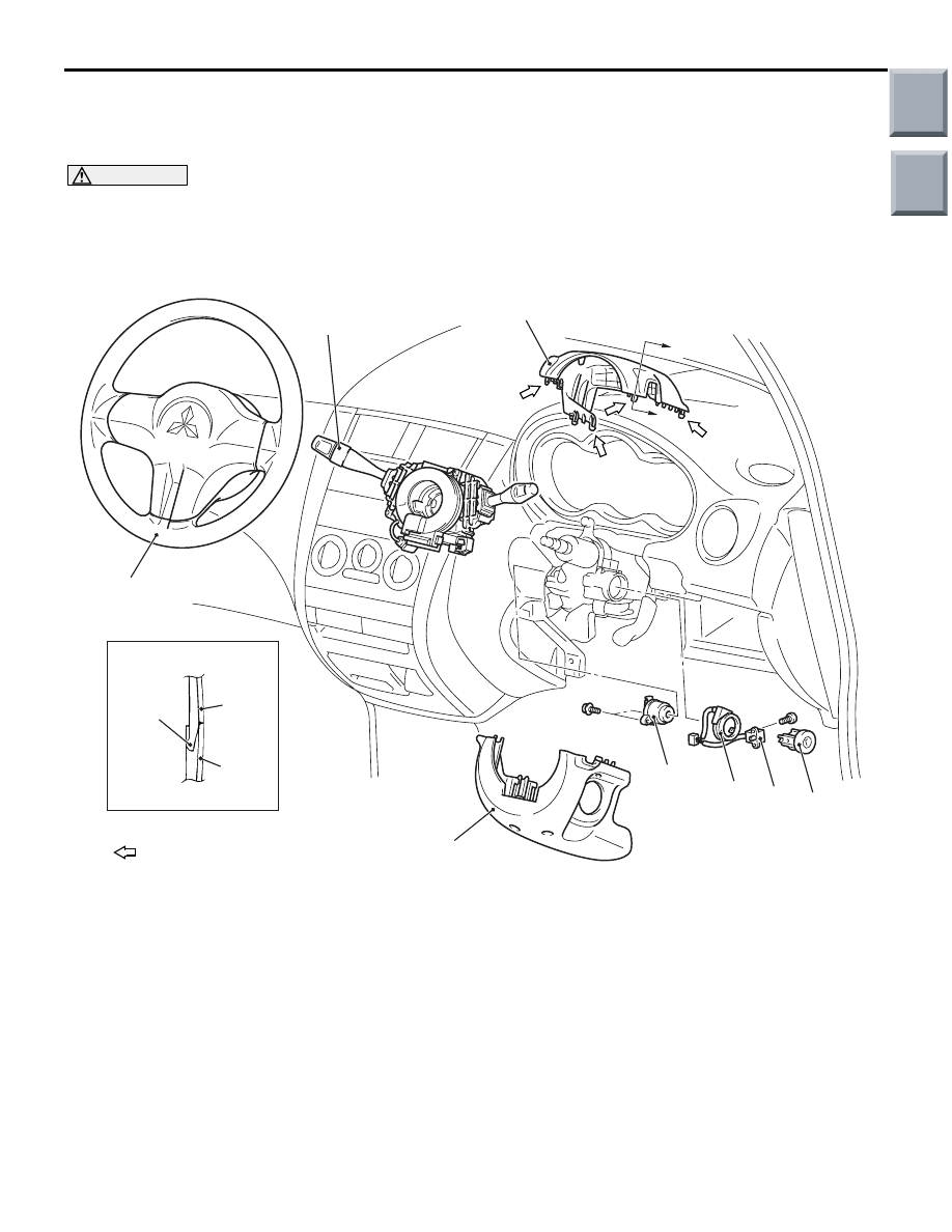
Section A – A
Claw
NOTE
: Claw position
When removing and installing the steering wheel, do not let it bump against the air bag
module.
Main
Index
Group
TOC

AC509610
9
AB
5.0 ± 1.0 N·m
Ignition switch removal steps
•
Lower panel (Refer to GROUP 52A,
Instrument panel assembly
.)
1.
Steering column upper cover
2.
Steering column lower cover
3.
Steering wheel (Refer to GROUP
37, Steering wheel
.)
4.
Column switch
•
Selector lever assembly <Vehicles
for smart shift> (Refer to GROUP
23A, Transmission control
5.
Ignition switch
6.
Key reminder switch
7.
Key ring
<<
A
>>
8.
Steering lock cylinder
Immobiliser-ECU removal steps
•
Upper centre panel, Lower centre
panel, Parcel box bracket, Heater
control panel, Centre console
(Refer to GROUP 52A, Instrument
panel assembly
.)
9.
Immobiliser-ECU
IGNITION SWITCH
CHASSIS ELECTRICAL
54A-26
Ignition switch removal steps
Main
Index
Group
TOC

IGNITION SWITCH
CHASSIS ELECTRICAL
54A-27
REMOVAL SERVICE POINT
<<A>> STEERING LOCK CYLINDER
REMOVAL
1. Insert the key in the steering lock cylinder and turn
it to the "ACC" position.
AC206363AC
Lock pin
2. Using a small Phillips head screwdriver, pull the
steering lock cylinder toward you.
INSPECTION
M1543019504588
IGNITION SWITCH CONTINUITY CHECK
AC206924
;;;;
;;;;
yyyy
yyyy
3
6
1
4
2
5
AB
Disconnect ignition switch connector without remov-
ing the ignition switch. Then check the continuity.
Switch position
Tester
connection
Specified
condition
"LOCK" (OFF)
1
− 2, 1 − 4, 1 − 5,
1
− 6
Open
circuit
"ACC"
1 -6
Continuity
exists (2
Ω
or less)
"ON"
1
− 2, 1 − 4, 1 − 6,
2
− 4, 2 − 6, 4 − 6
Continuity
exists (2
Ω
or less)
"START"
1
− 2, 1 − 5, 2 − 5 Continuity
exists (2
Ω
or less)
KEY REMINDER SWITCH CONTINUITY
CHECK
AC206923
6
2
7
5
1
3 4
AB
Disconnect key reminder switch connector without
removing the ignition switch and key reminder
switch. Then check the continuity.
Status of ignition key
Tester
connection
Specified
condition
Removed
4
− 6
Continuity
exists (2
Ω
or less)
Inserted
4
− 6
Open
circuit
Main
Index
Group
TOC

COMBINATION METER
CHASSIS ELECTRICAL
54A-28
COMBINATION METER
SERVICE SPECIFICATIONS
M1543000300937
Item
Standard
value
Limit
Speedometer indicating tolerance km/h
20
20 - 24
−
40
40 - 44
−
80
80.5 - 85.5
−
120
121.5 - 127.5
−
160
162.5 - 169.5
−
200
203.5 - 211.5
−
The speedometer needle fluctuation km/h (Vehicle speed is 35 km/h or more)
−
± 3
Tachometer indicating tolerance r/min
700
700
± 70
(2,000)
(2,000
± 80)
3,000
3,000
± 120
(4,000)
(4,000
± 120)
5,000
5,000
± 120
−
6,000
6,000
± 120
−
Fuel gauge unit resistance
Ω
Stopper position "F"
13.0
± 1
−
Stopper position "E"
120.0
± 1
−
Fuel gauge unit float height mm
Stopper position "F" (highest A)
57.7
−
Stopper position "E" (lowest B)
215
−
Main
Index
Group
TOC
Нет комментариевНе стесняйтесь поделиться с нами вашим ценным мнением.
Текст