Mitsubishi Colt Ralliart. Manual — part 479

COMBINATION METER
CHASSIS ELECTRICAL
54A-61
NOTE:
*
indicates that the slowest vehicle speed is 5
km/h.
C6
CVT indicator: L
Shift position : Other than
L position
OFF
Shift position : L position ON
D3
ASC OFF indicator lamp ASC OFF indicator lamp
: OFF
OFF
ASC OFF indicator lamp
: ON
ON
D4
ASC indicator lamp
ASC indicator lamp :
OFF
OFF
ASC indicator lamp : ON ON
Item No.
Check items
Check conditions
Normal conditions
Main
Index
Group
TOC

COMBINATION METER
CHASSIS ELECTRICAL
54A-62
ACTUATOR TEST TABLE
M1543007400333
Item
No.
Check items
Test content
Check conditions
Normal conditions
80
Speedometer
Set the speedometer
to 0 km/h
Turn the ignition
switch to the ON
position.
Speedometer shows 0
km/h
81
Set the speedometer
to 40 km/h
Speedometer shows
40 km/h
82
Set the speedometer
to 100 km/h
Speedometer shows
100 km/h
84
Tachometer
Set the tachometer to
0 r/min
Turn the ignition
switch to the ON
position.
Tachometer shows 0
r/min
85
Set the tachometer to
2000 r/min
Tachometer shows
2000 r/min
86
Set the tachometer to
5000 r/min
Tachometer shows
5000 r/min
88
Water thermometer
Set the water
thermometer to 0
°C
Turn the ignition
switch to the ON
position.
Water thermometer
shows 0
°C
89
Set the water
thermometer to 85
°C
Water thermometer
shows 85
°C
8A
Set the water
thermometer to 126
°C
Water thermometer
shows 126
°C
8C
Fuel gauge
Set the fuel gauge to 0
%
Turn the ignition
switch to the ON
position.
Fuel gauge shows 0 %
8D
Set the fuel gauge to
50 %
Fuel gauge shows 50
%
8E
Set the fuel gauge to
100 %
Fuel gauge shows 100
%
90
Fuel gauge (target
value)
Set the fuel gauge to 0
%
Turn the ignition
switch to the ON
position.
Fuel gauge shows 0 %
91
Set the fuel gauge to
50 %
Fuel gauge shows 50
%
92
Set the fuel gauge to
100 %
Fuel gauge shows 100
%
93
Combination meter
illumination
Set the combination
meter illumination to 0
%
Turn the ignition
switch to the ON
position.
Combination meter
illumination is 0 %
94
Set the combination
meter illumination to
50 %
Combination meter
illumination is 50 %
95
Set the combination
meter illumination to
100 %
Combination meter
illumination is 100 %
Main
Index
Group
TOC

COMBINATION METER
CHASSIS ELECTRICAL
54A-63
A0
Indicator lamp and
warning lamp
Illuminate the indicator
lamp and the warning
lamp.
Turn the ignition
switch to the ON
position.
The turn-signal lamps,
the door lamps, the fog
lamps, the electric
power steering
warning lamp, the
high-beam indicator,
the brake warning
lamp, the high coolant
temperature warning
lamp, the CHECK
ENGINE warning
lamp, the charge
warning lamp, the oil
pressure indicator
lamp, the SRS, the
ABS, the seat belt and
the fuel warning lamp
illuminate.
A1
Extinguish the
indicator lamps and
the warning lamps.
The turn-signal lamps,
the door lamps, the fog
lamps, the electric
power steering
warning lamp, the
high-beam indicator,
the brake warning
lamp, the high coolant
temperature warning
lamp, the CHECK
ENGINE warning
lamp, the charge
warning lamp, the oil
pressure indicator
lamp, the SRS, the
ABS, the seat belt and
the fuel warning lamp
extinguish.
A2
Shift indicator lamp
Illuminate the shift
indicator lamp.
Turn the ignition
switch to the ON
position.
The shift indicator
lamp illuminates.
A3
Extinguish the shift
indicator lamp.
The shift indicator
lamp extinguishes.
A5
lndicator lamp
Illuminate the indicator
lamp.
Turn the ignition
switch to the ON
position.
The tail lamp indicator
lamp illuminates.
A6
Extinguish the
indicator lamp.
The tail lamp indicator
lamp extinguishes.
Item
No.
Check items
Test content
Check conditions
Normal conditions
Main
Index
Group
TOC
COMBINATION METER
CHASSIS ELECTRICAL
54A-64
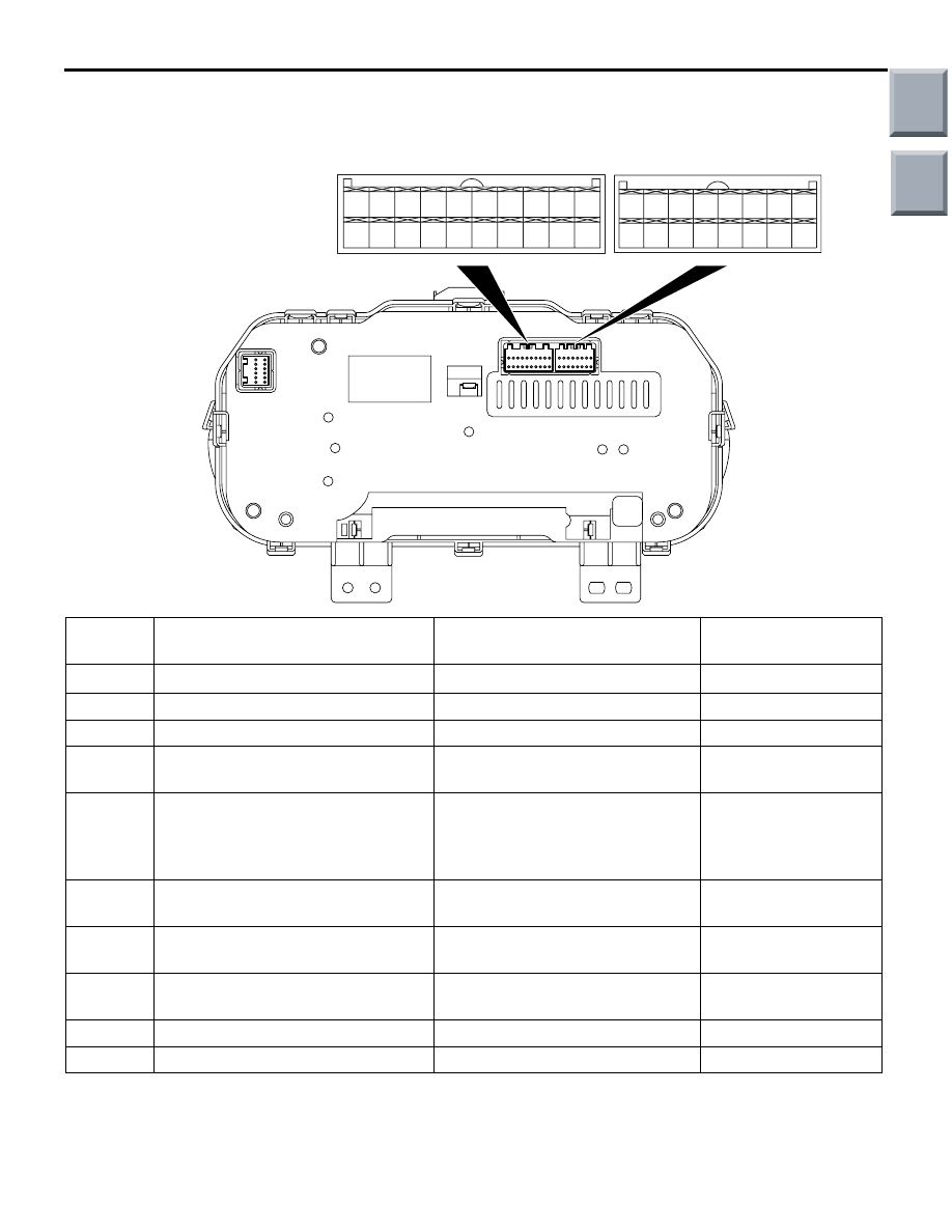
CHECK AT ECU TERMINALS
M1543007601255
AC206265
AF
35
34
252627
32
31
24
2223
33
29
21
30
36
28
20
19
18
17
7
6
15
14
4
3
1112 13
5
1
9 10
2
16
8
B-15
B-14
Terminal
No.
Check items
Check conditions
Normal conditions
22
Input of fuel gauge
Always
−
23
Illumination (earth)
Always
0 V
24
Illumination (power supply)
Illumination switch: ON
System voltage
25
Oil pressure switch
Ignition switch: ON and before
starting the engine
−
28
Input of parking brake switch and
brake fluid level switch
• Ignition switch: ON and parking
brake switch: ON
• Ignition switch: ON and brake
fluid level switch: ON
−
27
Input of seatbelt switch
Ignition switch: ON and the
driver's seat belt is unfastened.
−
31
Power supply from ignition switch
(IG1)
Ignition switch: ON
System voltage
32
Power supply from ignition switch
(IG2)
Ignition switch: ON
System voltage
33
Battery power supply
Always
System voltage
36
Earth
Always
0 V
Main
Index
Group
TOC
Нет комментариевНе стесняйтесь поделиться с нами вашим ценным мнением.
Текст