Mitsubishi Colt Ralliart. Manual — part 663
TROUBLESHOOTING
AUTOMATIC AIR CONDITIONER
55B-13
Step 2. M.U.T.-III data list.
Check that the following service data display con-
tents are normal. (Refer to
).
• Item 06: Photo sensor
Q: Is the check result normal?
YES :
Go to Step 3.
NO :
Go to Step 4.
Step 3. Recheck the trouble symptom
Q: Is the check result normal?
YES :
The trouble can be an intermittent
malfunction (Refer to GROUP 00, How to
Cope with Intermittent Malfunction
).
NO :
Replace the combination meter (meter and
A/C-ECU).
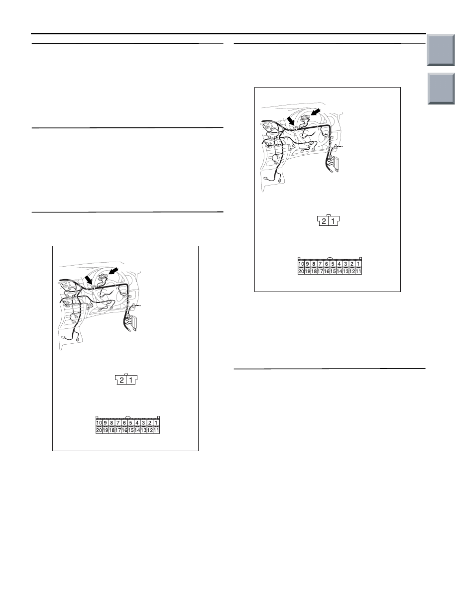
Step 4. Connector check: B-13 photo sensor
connector and B-15 combination meter
connector
AC313823 AM
Connectors: B-13, B-15
Harness side
B-15 (B)
B-15
B-13 (B)
B-13
Q: Is the check result normal?
YES :
Go to Step 5.
NO :
Repair the connector.
Step 5. Check the wiring harness between B-13
photo sensor connector (terminal 1 and 2) and
B-15 combination meter connector (terminal 14
and 6).
AC313823 AM
Connectors: B-13, B-15
Harness side
B-15 (B)
B-15
B-13 (B)
B-13
• Check the A/C compressor relay power supply
line for open circuit.
Q: Is the check result normal?
YES :
Go to Step 6.
NO :
Repair the wiring harness. Check that the
air conditioner works normally.
Step 6. Replace the photo sensor and recheck
the trouble symptom
Check that the air conditioner works normally.
Q: Is the check result normal?
YES :
This diagnosis is complete.
NO :
Replace the combination meter (meter and
A/C-ECU).
Main
Index
Group
TOC

TROUBLESHOOTING
AUTOMATIC AIR CONDITIONER
55B-14
Inspection Procedure 2: The blower does not work
FUSIBLE
LINK
6
IGNITION
SWITCH (IG2)
BLOWER
RELAY
COMBINATION
METER
METER AND A/C-ECU
BLOWER MOTOR
DRIVE CIRCUIT
BLOWER
MOTOR
POWER
TRANSISTER
Wire colour code
B : Black LG : Light green G : Green L : Blue W : White Y : Yellow SB : Sky blue
BR : Brown O : Orange GR : Gray R : Red P : Pink V : Violet
Blower Motor Circuit
COMMENTS ON TROUBLE SYMPTOM
If the blower motor does not operate, the blower
motor circuit system may be defective.
POSSIBLE CAUSES
• Malfunction of the blower motor.
• Malfunction of the power transistor.
• Malfunction of the combination meter (meter and
A/C-ECU)
• Damaged the wiring harness or connectors
Main
Index
Group
TOC

TROUBLESHOOTING
AUTOMATIC AIR CONDITIONER
55B-15
DIAGNOSIS PROCEDURE
Step 1. M.U.T.-III actuator test
Carry out the actuator test. (Refer to
• Item 01, 02, 03: blower fan
Q: Does the blower motor work normally?
YES :
Go to Step 2.
NO :
Go to Step 3.
Step 2. Recheck the trouble symptom
Q: Is the check result normal?
YES :
Intermittent malfunction (GROUP 00
− How
to Cope with Intermittent Malfunction
).
NO :
Go to Step 19.
Step 3. Connector check: B-116 blower relay
connector
AC313824
Connector: B-116
AD
Junction block side
Junction block (Front view)
Q: Is the check result normal?
YES :
Go to Step 4.
NO :
Repair the connector.
Step 4. Check the blower relay.
Refer to GROUP 55A, On-vehicle Service
− Power
relay check
.
Q: Is the blower relay in good condition?
YES :
Go to Step 5.
NO :
Replace the blower relay.
Step 5. Connector check: B-10 blower motor
connector and B-15 combination meter
connector
AC313823AN
Connectors: B-10, B-15
Harness side
B-15 (B)
B-15
B-10
B-10
Harness side
Q: Is the check result normal?
YES :
Go to Step 6.
NO :
Repair the connector.
Main
Index
Group
TOC
TROUBLESHOOTING
AUTOMATIC AIR CONDITIONER
55B-16
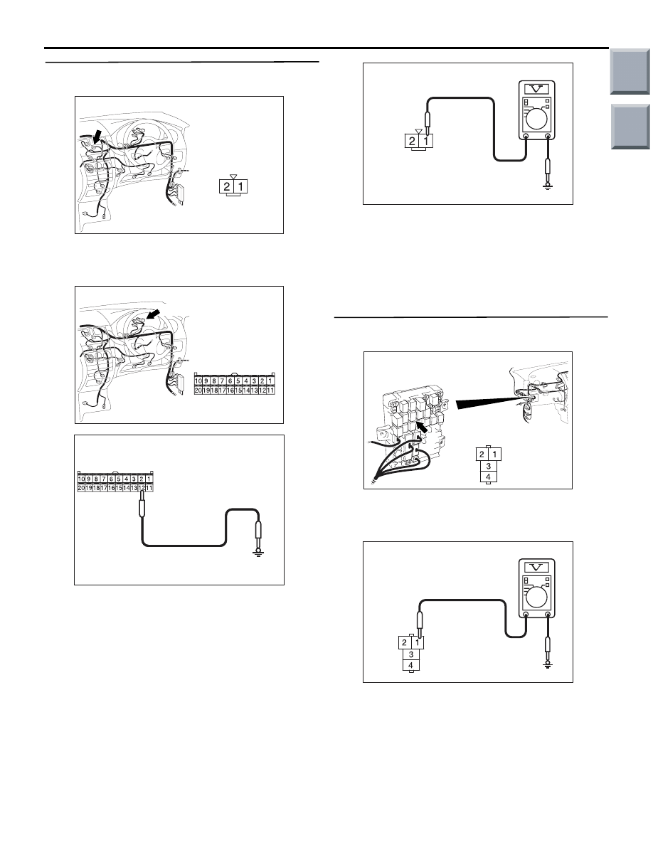
Step 6. Voltage measurement at the B-10 blower
motor controller connector.
AC313822
Connector: B-10
AK
Harness side
(1) Disconnect the connector, and measure at the
wiring harness side.
(2) Turn the ignition switch to the ON position.
AC313822 AB
Connector: B-15
Harness side
B-15 (B)
AC309471
AC309471AM
Connector B-15
(Harness side)
(3) Disconnect combination meter connector B-15,
and earth terminal 12.
AC310507
Connector B-10
(Harness side)
FH
(4) measure the voltage between terminal 1 and
body earth.
OK: System voltage
Q: Is the check result normal?
YES :
Go to Step 13.
NO :
Go to Step 7.
Step 7. Voltage measurement at B-116 blower
relay connector.
AC313824
Connector: B-116
AD
Junction block side
Junction block (Front view)
(1) Remove the relay, and measure at the junction
block side.
(2) Turn the ignition switch to the ON position.
AC310507 EI
Connector C-116
(Junction block side)
(3) Voltage between terminal 1 and body earth.
OK: System voltage
Q: Is the check result normal?
YES :
Go to Step 9.
NO :
Go to Step 8.
Main
Index
Group
TOC
Нет комментариевНе стесняйтесь поделиться с нами вашим ценным мнением.
Текст