Mitsubishi Colt Ralliart. Manual — part 635

TROUBLESHOOTING
ACTIVE STABILITY CONTROL SYSTEM (ASC)
35C-85
TROUBLE SYMPTOM CHART
M1357001000013
CAUTION
During diagnosis, a diagnosis code associated with other system may be set when the ignition switch
is turned on with connector(s) disconnected. On completion, check if the diagnosis code is set. If the
diagnosis code has been set, erase that code.
SYMPTOM PROCEDURES
Inspection Procedure 1: Cannot communicate with ASC-ECU using the M.U.T.-III
COMMENTS ON TROUBLE SYMPTOM
If the M.U.T.-III cannot communicate with the
ASC-ECU, the CAN bus lines may be defective.
When malfunction occurs in the ASC-ECU power
supply circuit and earth circuit, the CAN bus diagno-
sis detects the abnormality. This symptom also
appears when an incorrect vehicle model is selected
on the M.U.T.-III.
PROBABLE CAUSES
• Damaged wiring harness and connectors
• ASC-ECU malfunction
DIAGNOSTIC PROCEDURE
STEP 1. M.U.T.-III selected vehicle model
confirmation
Confirm which vehicle model is selected on the
M.U.T.-III vehicle information screen.
Q: Is the correct vehicle model selected?
YES :
Go to Step 2.
NO :
Input the vehicle information correctly.
STEP 2. M.U.T.-III CAN bus diagnostics
Use the M.U.T.-III to diagnose the CAN bus lines.
Q: Is the check result normal?
YES :
Replace the ASC-ECU.
NO :
Repair the CAN bus lines. (Refer to GROUP
54D
Trouble symptom
Inspection
procedure
number
Reference page
Cannot communicate with ASC-ECU using the M.U.T.-III
1
ASC-ECU power supply circuit system
2
The ABS warning lamp and the ASC indicator lamp don't illuminate when
the ignition switch is turned ON.
3
ABS warning lamp and ASC indicator lamp does not extinguish after the
engine is started.
4
Brake warning lamp does not illuminate at all.
5
Brake warning lamp does not illuminate when the parking brake is
operated. (illuminates when the bulb check is performed.)
6
Brake warning lamp does not illuminate when the brake fluid level is low
(illuminates when the parking brake is operated).
7
Brake warning lamp does not extinguish when the ignition switch is ON
(remains illuminated).
8
Stability control system operates too frequently (no diagnosis code is set). 9
Steering wheel sensor power supply system
10
G and yaw rate sensor power supply circuit
11
Main
Index
Group
TOC

TROUBLESHOOTING
ACTIVE STABILITY CONTROL SYSTEM (ASC)
35C-86
Inspection Procedure 2: ASC-ECU power supply circuit malfunction
OPERATION
• The ASC-ECU is energised by the ignition switch
(IG1) through multi-purpose fuse 40 and the
ASC-ECU terminal No. 40.
• When malfunction occurs in ASC-ECU power
supply, the communication with M.U.T.-III
becomes unavailable.
PROBABLE CAUSES
• Damaged wiring harness and connectors
• Battery failure
• Charging system failed
• ASC-ECU malfunction
DIAGNOSTIC PROCEDURE
STEP 1. Battery terminal voltage measurement
(1) Ignition switch: ON
(2) Engine: Started
(3) Measure the voltage between the battery
terminals.
OK: 10V or more
Q: Is the check result normal?
YES :
Go to Step 2.
NO :
Diagnose the charging system. (Refer to
GROUP 16
− On-vehicle Service
ASC-ECU Power Source Circuit
Wire colour code
B : Black LG : Light green G : Green L : Blue W : White Y : Yellow SB : Sky blue
BR : Brown O : Orange GR : Grey R : Red P : Pink V : Violet PU : Purple
IGNITION
SWITCH (IG1)
ASC-ECU
Main
Index
Group
TOC

TROUBLESHOOTING
ACTIVE STABILITY CONTROL SYSTEM (ASC)
35C-87
STEP 2. Connector check: A-05 ASC-ECU
connector
Q: Is the check result normal?
YES :
Go to Step 3.
NO :
Repair the damaged connector.
STEP 3. Voltage measurement: A-05 ASC-ECU
connector
(1) Disconnect A-05 ASC-ECU connector, and
connect the ABS check harness (Special tool:
MB991984) to the ASC-ECU side connector and
the harness side connector.
(2) Ignition switch: ON
(3) Engine: Started
(4) Measure the voltage between the ABS check
harness (Special tool: MB991984) connector
terminal No. 40 and the body earth.
OK: 10 V or more
Q: Is the check result normal?
YES :
Go to Step 4.
NO :
Repair the harness wire between A-05
ASC-ECU connector terminal No. 40 and
the ignition switch (IG1).
AC601083
Connector: A-05
AB
A-05(Black)
Harness side
AC601083
Connector: A-05
AB
A-05(Black)
Harness side
AC601086AD
MB991984
ASC-ECU
Check connector
ASC-ECU harness connector
Main
Index
Group
TOC
TROUBLESHOOTING
ACTIVE STABILITY CONTROL SYSTEM (ASC)
35C-88
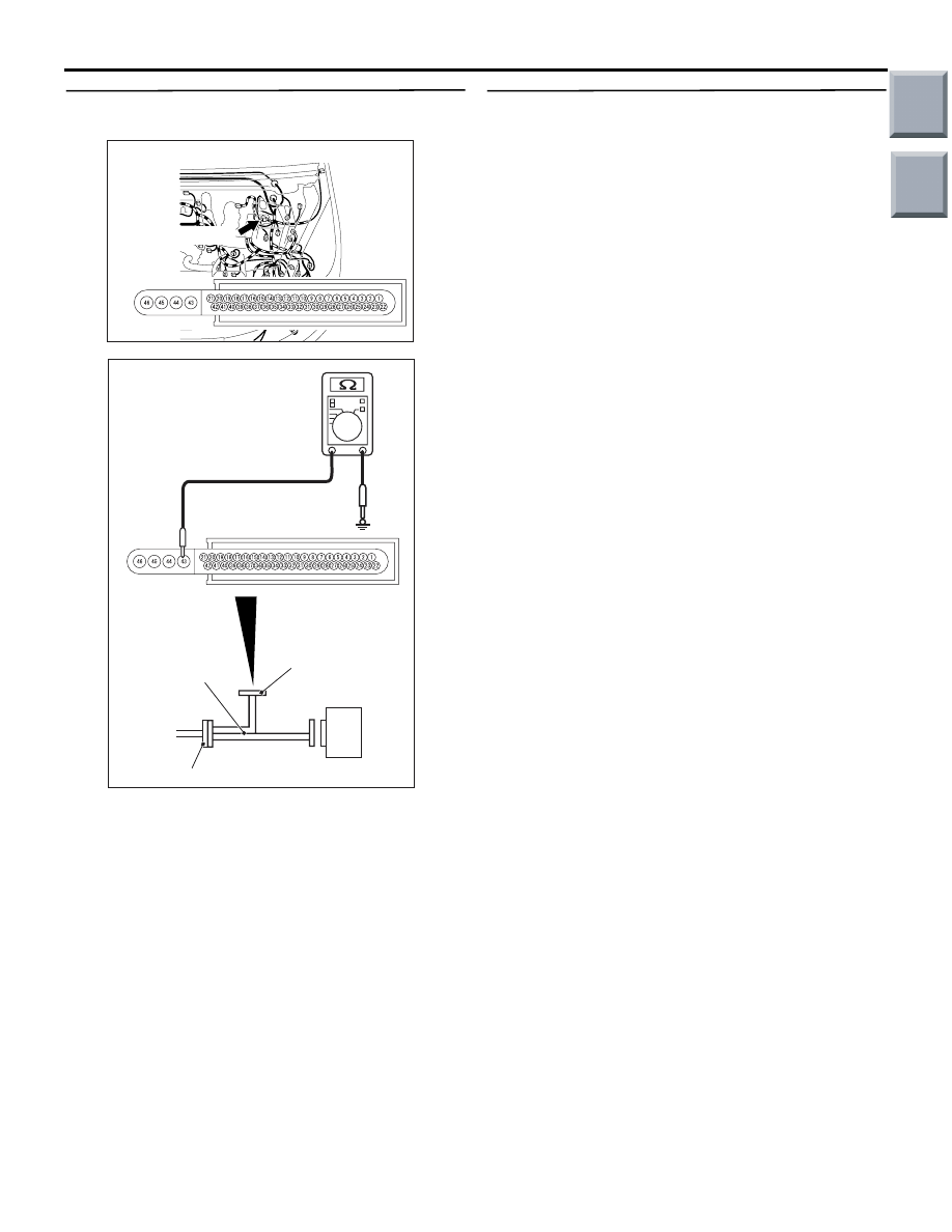
STEP 4. Measure the resistance at A-05 ASC-ECU
connector.
(1) Disconnect the A-05 ASC-ECU connector, and
connect the ABS check harness (Special tool:
MB991984) to the harness side connector.
NOTE: . Do not connect the ABS check harness
(Special tool: MB991984) to the ASC-ECU.
(2) Measure the resistance between A-05 ASC-ECU
connector terminal No. 43 and the body earth.
OK: Continuity exists (2
Ω or less)
Q: Is the check result normal?
YES : .
Go to Step 5.
NO : .
Repair the harness wire between A-05
ASC-ECU connector terminal No. 43 and
the body earth.
STEP 5. Retest the system.
Q: Can the ASC-ECU communicate with the M.U.T.-III?
YES :
Intermittent malfunction (Refer to GROUP
00
− How to Cope with Intermittent
.)
NO :
Replace the ASC-ECU.
AC601083
Connector: A-05
AB
A-05(Black)
Harness side
AC601085AI
MB991984
ASC-ECU
Check connector
ASC-ECU harness connector
Main
Index
Group
TOC
Нет комментариевНе стесняйтесь поделиться с нами вашим ценным мнением.
Текст