Mitsubishi Colt Ralliart. Manual — part 691
TROUBLESHOOTING
MULTIPORT FUEL INJECTION (MPI) <4G1>
13B-89
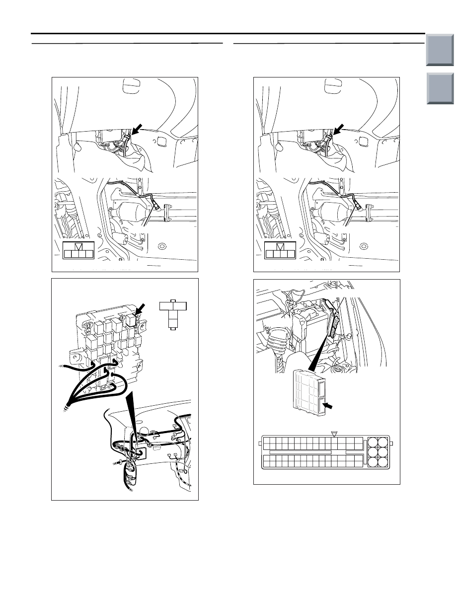
STEP 9. Check harness between B-53 (terminal
No. 4) oxygen sensor (rear) connector and B-106
(terminal No. 4) engine control relay connector.
NOTE: Before checking harness, check intermediate
connector B-112, and repair if necessary.
• Check power supply line for damage.
Q: Is the check result normal?
YES :
Go to Step 10 .
NO :
Repair the damaged harness wire.
STEP 10. Check harness between B-53 (terminal
No. 3) oxygen sensor (rear) connector and A-08
(terminal No. 79) engine-ECU connector.
• Check earthing line for damage.
Q: Is the check result normal?
YES :
Go to Step 11 .
NO :
Repair the damaged harness wire.
AK402019
3
2
1
4
Oxygen sensor (rear)
Connector: B-53
B-53 Harness side connector
AC
B-53
3
2
1
4
AK402084
J/B side
connector
B-106
Connector: B-106
J/B (front side)
AC
AK402019
3
2
1
4
Oxygen sensor (rear)
Connector: B-53
B-53 Harness side connector
AC
B-53
AK402725
77
78
79
80
81
82
83
84
92
93
94
95
96
97
98
99
85
86
87
88
89
90
91
100
101
102
103
104
105
106
115
116
117
118
119
120
121
107
108
109
110
111
112
113
114
130
131
132
133
134
135
136
122
123
124
125
126
127
128
129
72 71
74 73
76 75
R
AI
A-08
Connector:
A-08
A-08 Special tool power plant ECU check
harness
Engine-ECU
Battery
Main
Index
Group
TOC
TROUBLESHOOTING
MULTIPORT FUEL INJECTION (MPI) <4G1>
13B-90
STEP 11. M.U.T.-III diagnosis code.
• Reconfirmation of diagnosis code.
Q: Is the diagnosis code set?
YES :
Replace engine-ECU.
NO :
Intermittent malfunction (Refer to GROUP
00
− How to Use
Troubleshooting/Inspection Service Points
−
How to Cope with Intermittent Malfunctions
).
Code No. P0170: Abnormal Fuel System
OPERATION
• Refer to Code No. P0201: No. 1 Injector System
• Refer to Code No. P0202: No. 2 Injector System
• Refer to Code No. P0203: No. 3 Injector System
.
• Refer to Code No. P0204: No. 4 Injector System
.
FUNCTION
• If the fuel system goes out of order, the fuel cor-
rection value will become larger.
• The engine-ECU checks whether the fuel correc-
tion value is within a specified range.
TROUBLE JUDGEMENT
Check Condition
• In learning air-fuel ratio
Judgement Criterion
• For more than 5 seconds, compensation value in
fuel injection amount is too low.
Or
• For more than 5 seconds, compensation value in
fuel injection amount is too high.
PROBABLE CAUSES
• Failed fuel supply system
• Failed oxygen sensor
• Failed intake air temperature sensor
• Failed engine coolant temperature sensor
• Failed air flow sensor
• Failed barometric pressure sensor
• Air drawn in from intake hose and inlet manifold
• Exhaust leak from exhaust manifold
• Failed throttle body (throttle valve area) fouled
• Failed injector
• Failed purge control solenoid valve
• Fuel pressure improper
• Failed engine-ECU
DIAGNOSIS PROCEDURE
STEP 1. M.U.T.-III diagnosis code
Q: Is any other diagnosis code than P0170 output?
YES :
Refer to Inspection Chart for Diagnosis
Code
.
NO :
Go to Step 2.
STEP 2. M.U.T.-III data list
• Refer to Data List Reference Table
.
a. Item 12: Air flow sensor
b. Item 13: Intake air temperature sensor
c. Item 21: Engine coolant temperature sensor
d. Item 25: Barometric pressure sensor
Q: Is the check result normal?
YES :
Go to Step 3.
NO :
Perform the diagnosis code classified check
procedure on the sensor that has shown an
abnormal data value (Refer to Inspection
Chart for Diagnosis Code
STEP 3. Check for ingress of air from intake hose
and inlet manifold.
Q: Is the check result normal?
YES :
Go to Step 4.
NO :
Repair.
STEP 4. Check for leakage of exhaust emission
from exhaust manifold.
Q: Is the check result normal?
YES :
Go to Step 5.
NO :
Repair.
Main
Index
Group
TOC
TROUBLESHOOTING
MULTIPORT FUEL INJECTION (MPI) <4G1>
13B-91
STEP 5. Check throttle body (throttle valve
portion) for foul.
Q: Is the check result normal?
YES :
Go to Step 6.
NO :
Clean throttle body (throttle valve portion)
(Refer to
).
STEP 6. M.U.T.-III data list
• Refer to Data List Reference Table
.
a. Item 11: Oxygen sensor (front)
Q: Is the check result normal?
YES :
Go to Step 7.
NO :
Check oxygen sensor system (Refer to
Code No. P0130
STEP 7. Check injector itself.
• Check injector itself (Refer to
).
Q: Is the check result normal?
YES :
Go to Step 8.
NO :
Replace injector.
STEP 8. Check purge control solenoid valve
itself.
• Check purge control solenoid valve itself (Refer
to GROUP 17
− Emission Control System −
Evaporative Emission Control System
− Purge
Control Solenoid Valve
).
Q: Is the check result normal?
YES :
Go to Step 9.
NO :
Replace purge control solenoid valve.
STEP 9. Fuel pressure measurement
• Fuel pressure measurement (Refer to
).
Q: Is the check result normal?
YES :
Replace engine-ECU.
NO :
Repair.
Main
Index
Group
TOC
TROUBLESHOOTING
MULTIPORT FUEL INJECTION (MPI) <4G1>
13B-92
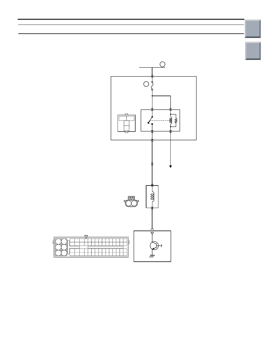
Code No. P0201: No. 1 injector System
OPERATION
• Power is supplied to the injector (terminal No. 1)
through the engine control relay (terminal No. 4).
• The engine-ECU (terminal No. 8) turns on the
power transistor in the unit to activate the injector
(terminal No. 2).
AK402684
2
1
3
1
2
4
19
21
20
18
17
16
15
14
1213
11
8 9
L
10
37
52 53 54 555657585960616263646566
38 39 404142434445464748495051
22 23 24 252627282930313233343536
7
5
3
1
6
4
2
A-114
AN
B-106
A-17
B-112
B-108
Engine
control
relay
Injector
No. 1
A-102
(MU802062)
4
6
4
1
2
2
8
No. 1 Injector Circuit
R
R
Wire colour code
B: Black LG: Light green G: Green L: Blue W: White Y: Yellow SB: Sky blue BR: Brown O: Orange GR: Gray
R: Red P: Pink V: Violet P: Purple
Y-V
3
1
1
1
R
Fusible link
16
20A
J/B
To engine-ECU
Engine-ECU
Main
Index
Group
TOC
Нет комментариевНе стесняйтесь поделиться с нами вашим ценным мнением.
Текст