Mitsubishi Colt Ralliart. Manual — part 452

TROUBLESHOOTING
POWER STEERING
37-75
DIAGNOSIS PROCEDURE
STEP 1. Check the connectors and terminals.
•
AC314189AE
Connector: B-37, B-38
B-37
B-38
Harness side
B-37
21
22
B-38
Electric power steering-ECU connectors B-37 and
B-38
Check the connectors above for improper engage-
ment, terminal damage or terminal drawn in the con-
nector case.
Q: Are the connectors and terminals in good
condition?
YES :
Go to Step 2.
NO :
Repair the connector(s) or terminal(s).
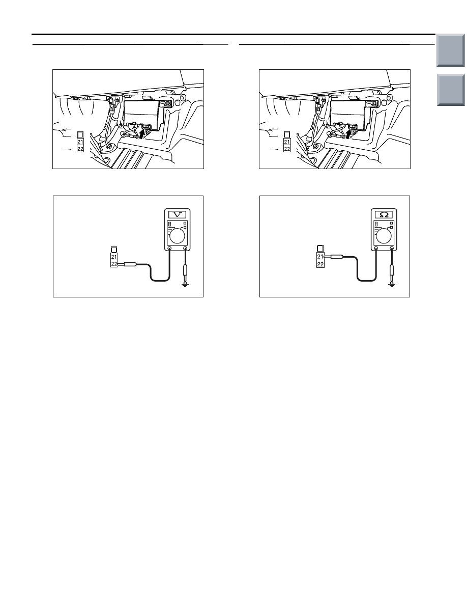
STEP 2. Voltage measurement at electric power
steering-ECU connector B-37.
•
AC314189AF
Connector: B-37
Harness side
Disconnect the connector, and measure at the wiring
harness side.
• Ignition Switch: ON
•
AC313972 BW
Harness side
B-37
Measure the voltage between electric power steer-
ing-ECU connector B-37 terminal No.5 and body
earth
OK: system voltage
Q: Is the check result normal?
YES :
Go to Step 3.
NO :
Go to Step 5.
Main
Index
Group
TOC
TROUBLESHOOTING
POWER STEERING
37-76
STEP 3. Voltage measurement at electric power
steering-ECU connector B-38.
•
AC314189
AC314189
AC314189AG
Connector: B-38
Harness side
Disconnect the connector, and measure at the wiring
harness side.
•
AC313972 BX
Harness side
connector B-38
(Rear view)
Measure the voltage between electric power steer-
ing-ECU connector B-38 terminal No.22 and
body earth
OK: system voltage
Q: Is the check result normal?
YES :
Go to Step 4.
NO :
Go to Step 6.
STEP 4. Resistance measurement at electric
power steering-ECU connector B-38.
•
AC314189
AC314189
AC314189AG
Connector: B-38
Harness side
Disconnect the connector, and measure at the wiring
harness side.
•
AC313972 BY
Harness side
connector B-38
(Rear view)
Measure the resistance between electric power
steering-ECU connector B-38 terminal No.21 and
body earth
OK: Continuity exists (2
Ω or less)
Q: Is the check result normal?
YES :
Go to Step 8.
NO :
Go to Step 7.
Main
Index
Group
TOC
TROUBLESHOOTING
POWER STEERING
37-77
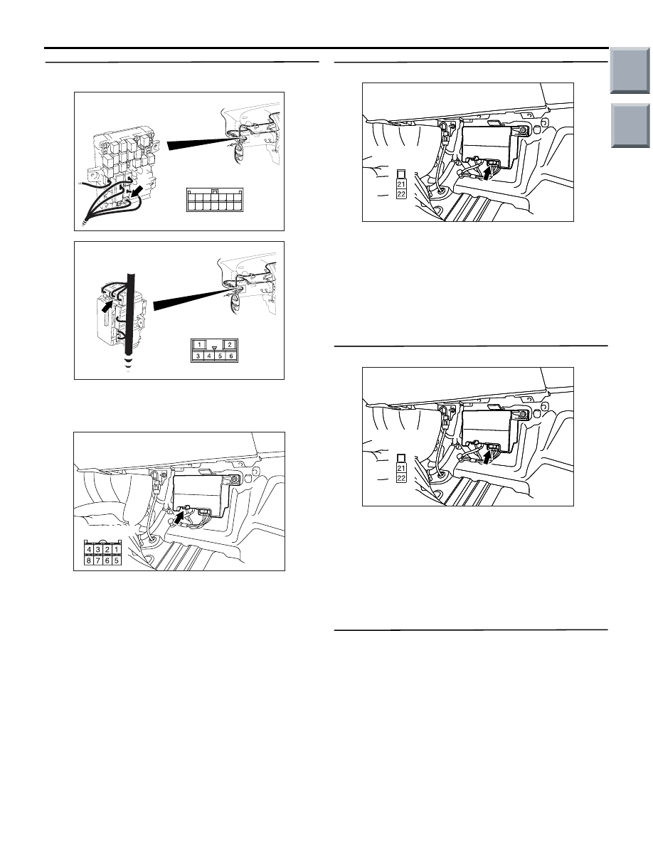
STEP 5. Check the wiring harness wires.
NOTE:
AC313870AI
Connector: B-110
Junction Block (Front view)
Junction block side
12
5
9
8
1 2
1011
3 4
14
13
6 7
AC313872AJ
Connector: B-129
Junction Block (Rear view)
Junction block side
Prior to the wiring harness inspection, check junction
block connectors B-110 and B-129, and repair if nec-
essary.
•
AC314189AF
Connector: B-37
Harness side
The harness wire between electric power steer-
ing-ECU connector B-37 and ignition switch (IG1)
B-141
Check the harness wire above for damage or other
problem.
Q: Is the wiring harness in good condition?
YES :
Go to Step 8.
NO :
Repair the wiring harness.
STEP 6. Check the wiring harness wires.
•
AC314189
AC314189
AC314189AG
Connector: B-38
Harness side
Harness wire between electric power steering-ECU
connector B-38 and fusible link No.22
Check the harness wire above for damage or other
problem.
Q: Is the wiring harness in good condition?
YES :
Go to Step 8.
NO :
Repair the wiring harness.
STEP 7. Check the wiring harness wires.
•
AC314189
AC314189
AC314189AG
Connector: B-38
Harness side
Harness wire between electric power steering-ECU
connector B-38 and body earth
Check the harness wire above for damage or other
problem.
Q: Is the wiring harness in good condition?
YES :
Go to Step 8.
NO :
Repair the wiring harness.
STEP 8. Retest the system.
Q: Is the check result normal?
YES :
The malfunction is intermittent. Refer to
GROUP 00, How to Use
Troubleshooting/Inspection Service Points
−
How to Cope with Intermittent Malfunction
.
NO :
Replace the electric power steering-ECU
(Refer to
).
Main
Index
Group
TOC

TROUBLESHOOTING
POWER STEERING
37-78
Inspection Procedure 3: Although the electric power steering system warning lamp illuminates but
diagnosis code is not stored.
ENGINE-CVT-ECU
DIAGNOSIS
CONNECTOR
FRONT SIDE
COMBINATION
METER
ABS-ECU
EPS-ECU
Wire colour code
B : Black
LG : Light green
G : Green
L: Blue
W : White
Y: Yellow
SB : Sky blue
BR : Brown
O : Orange
GR : Grey
R : Red
P : Pink
V : Violet
PU: Purple
CAN Communication Circuit
Main
Index
Group
TOC
Нет комментариевНе стесняйтесь поделиться с нами вашим ценным мнением.
Текст