Mitsubishi Colt Ralliart. Manual — part 292
OUTPUT SHAFT
CONTINUOUSLY VARIABLE TRANSMISSION OVERHAUL
23B-41
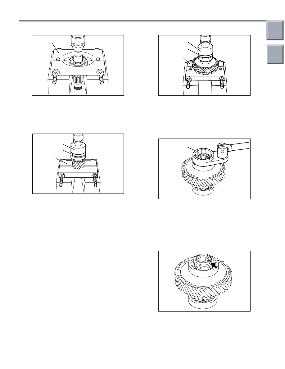
<<C>> BALL BEARING REMOVAL
AK401996
MD998801
AB
Use the special tool Bearing remover (MD998801) to
remove the ball bearing.
REASSEMBLY SERVICE POINTS
>>A<< BALL BEARING INSTALLATION
AK401997
MD998812
MD998801
MD998817
AC
Use the special tools to install the new ball bearing.
• Installer cap (MD998812)
• Installer adapter (MD998817)
• Bearing remover (MD998801)
>>B<< BALL BEARING INSTALLATION
AK401998
MD998812
MD998818
MD998801
AC
Use the special tools to install the new ball bearing.
• Installer cap (MD998812)
• Installer adapter (MD998818)
• Bearing remover (MD998801)
>>C<< LOCK NUT INSTALLATION
AK401994
MD998809
AC
1. Apply ATF to the thread portion of the lock nut
before installation.
2. Use the special tool Lock nut wrench (MD998809)
to tighten the lock nut to the specified torque of
190
± 20 N⋅m.
3. Loosen the lock nut one complete turn, then
tighten it again to the specified torque.
AK401993AC
4. Stake the lock nut securely into the notch in the
output shaft.
Main
Index
Group
TOC

DIFFERENTIAL
CONTINUOUSLY VARIABLE TRANSMISSION OVERHAUL
23B-42
DIFFERENTIAL
DISASSEMBLY AND REASSEMBLY
M1233213000110
AK202464
135 ± 5 N·m
1
2
6
5
3
4
7
10
6
8
9
9
7
AC
Apply automatic
transmission fluid
to all moving parts
before installation.
Disassembly steps
>>
E
1.
Differential drive gear
<<
A
>>
>>
D
<<
2.
Ball bearing
<<
B
>>
>>
C
<<
3.
Ball bearing
>>
B
<<
4.
Lock pin
>>
A
<<
5.
Pinion shaft
>>
A
6.
Pinion
>>
A
7.
Washer
>>
A
8.
Side gear
>>
A
9.
Spacer
10. Differential case
Disassembly steps (Continued)
Main
Index
Group
TOC

DIFFERENTIAL
CONTINUOUSLY VARIABLE TRANSMISSION OVERHAUL
23B-43
DISASSEMBLY SERVICE POINTS
<<A>> BALL BEARING REMOVAL
AK202466
MD998801
AC
Use the special tool Bearing remover (MD998801) to
remove the ball bearing from the differential case.
<<B>> BALL BEARING REMOVAL
AK202465
MD998801
AC
Use the special tool Bearing remover (MD998801) to
remove the ball bearing from the differential case.
REASSEMBLY SERVICE POINTS
>>A<< SPACER/SIDE
GEAR/WASHER/PINION/PINION SHAFT
INSTALLATION
AK102817
1. Fit the spacer on the back side of each side gear.
2. Install the side gears fitted with the spacers into
the differential case.
NOTE: . Use spacers of a thickness of 0.93
−
1.00
mm when installing new side gears.
AK102818
3. Fit the washer on the back side of each pinion.
Mesh both the pinions simultaneously with the
side gears, then bring the pinions into position
inside the differential case while rotating them.
4. Insert the pinion shaft into the differential case
while aligning the lock pin holes.
AK102819
5. Measure the backlash between each side gear
and the pinion.
Standard value: 0.025
− 0.150 mm
6. If the backlash deviates from the standard value,
replace the spacer of the side gear with a one of
an appropriate thickness and measure the
backlash again for confirmation.
NOTE: The backlash on one side gear should be
equal to that on the other after adjustments.
Main
Index
Group
TOC
DIFFERENTIAL
CONTINUOUSLY VARIABLE TRANSMISSION OVERHAUL
23B-44
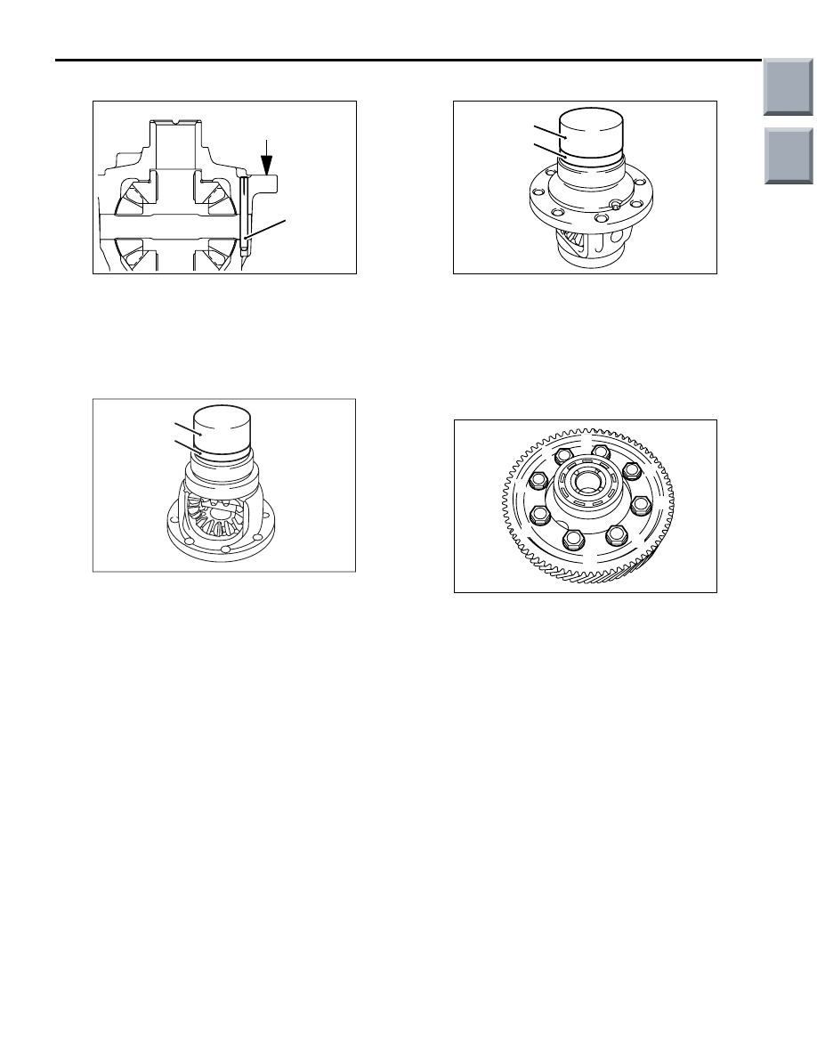
>>B<< LOCK PIN INSTALLATION
AK202467
Differential drive gear
mounting surface
Lock pin
AC
Insert the lock pins into the differential case using a
press with a force larger than 5 kN until their top
ends are lower than the differential drive gear mount-
ing surface.
>>C<< BALL BEARING INSTALLATION
AK202468
MD998812
MD998819
AC
Use the special tools to install the new ball bearing
on the differential case.
• Installer cap (MD998812)
• Installer adapter (40) (MD998819)
>>D<< BALL BEARING INSTALLATION
AK202469
MD998812
MD998819
AC
Use the special tools to install the new ball bearing
on the differential case.
• Installer cap (MD998812)
• Installer adapter (40) (MD998819)
>>E<< DIFFERENTIAL DRIVE GEAR
INSTALLATION
AK102822AC
8
1
3
5
7
2
4
6
1. Place the differential drive gear in position on the
differential case.
2. Apply ATF to each of the bolt and tighten the bolts
in the numbered sequence to the specified torque
of 135
± 5 N⋅m.
Main
Index
Group
TOC
Нет комментариевНе стесняйтесь поделиться с нами вашим ценным мнением.
Текст