Mitsubishi Colt Ralliart. Manual — part 227

REAR DRUM BRAKE <LS, VR>
BASIC BRAKE SYSTEM
35A-54
REASSEMBLY SERVICE POINT
>>A<< PISTON CUP/PISTON INSTALLA-
TION
1. Use alcohol or brake fluid DOT 3 or DOT 4 to
clean the wheel cylinder and the piston.
AC000929AL
MB991008
Piston
Lip must face upwards.
CAUTION
In order to keep the piston cup from becoming
twisted or slanted, slide the piston cup down
special tool installer (MB991008) slowly and care-
fully, without stopping.
2. Apply brake fluid DOT 3 or DOT 4 to the piston
cups and special tool installer (MB991008).
3. Set the piston cup on special tool with the lip of
the cup facing up. Fit the cup onto special tool,
and then slide it down the outside of special tool
into the piston groove.
Main
Index
Group
TOC
GROUP 35B
ANTI-SKID
BRAKING SYSTEM
(ABS)
CONTENTS
GENERAL INFORMATION . . . . . . . .
SERVICE SPECIFICATIONS. . . . . . .
SPECIAL TOOLS. . . . . . . . . . . . . . . .
TROUBLESHOOTING . . . . . . . . . . . .
STANDARD FLOW OF DIAGNOSTIC
TROUBLESHOOTING . . . . . . . . . . . . . . . .
NOTES WITH REGARD TO DIAGNOSIS .
ABS AND BRAKE WARNING LAMP
INSPECTION . . . . . . . . . . . . . . . . . . . . . . .
DIAGNOSIS FUNCTION. . . . . . . . . . . . . . .
INSPECTION CHART FOR
DIAGNOSIS CODE. . . . . . . . . . . . . . . . . . .
DIAGNOSIS TROUBLE CODE
PROCEDURES. . . . . . . . . . . . . . . . . . . . . .
INSPECTION CHART FOR TROUBLE
SYMPTOMS . . . . . . . . . . . . . . . . . . . . . . . .
INSPECTION PROCEDURE FOR
TROUBLE SYMPTOMS . . . . . . . . . . . . . . .
DATA LIST REFERENCE TABLE. . . . . . . .
ACTUATOR TEST REFERENCE TABLE . .
CHECK AT ABS-ECU . . . . . . . . . . . . . . . . .
ON-VEHICLE SERVICE . . . . . . . . . . .
HYDRAULIC UNIT CHECK . . . . . . . . . . . . .
IN THE EVENT OF A DISCHARGED
BATTERY . . . . . . . . . . . . . . . . . . . . . . . . . .
HYDRAULIC UNIT . . . . . . . . . . . . . . .
REMOVAL AND INSTALLATION . . . . . . . .
ABS SENSOR. . . . . . . . . . . . . . . . . . .
REMOVAL AND INSTALLATION . . . . . . . .
INSPECTION. . . . . . . . . . . . . . . . . . . . . . . .
Main
Index
Group
TOC

GENERAL INFORMATION
ANTI-SKID BRAKING SYSTEM (ABS)
35B-2
GENERAL INFORMATION
M1352000100636
FEATURES
The 4ABS ensures directional stability and controlla-
bility during hard braking.
For vehicles with this type of ABS, 4 sensors (4
channels) are installed on front and rear wheels
allowing independent left and right control.
The system has the following features:
• EBD (Electronic Brake-force Distribution system)
control has been added to provide the ideal brak-
ing force for the rear wheels.
• Magnetic encoder for detecting wheel speed has
been installed as a wheel speed sensor instead
of the rotor.
• For wiring harness saving and secure data com-
munication, CAN
*
bus has been adopted as a
tool of communication with another ECU.
NOTE:
*
For more information about CAN (Controller
Area Network), refer to GROUP 54D, General Infor-
mation
.
EBD CONTROL
In ABS, electronic control is used so the rear wheel
brake hydraulic pressure during braking is regulated
by rear wheel control solenoid valves in accordance
with the vehicle's rate of deceleration, and the front
and rear wheel slippage which are calculated from
the signals received from the various Wheel speed
sensors. EBD control is a control system which pro-
vides a high level of control for both vehicle braking
force and vehicle stability. The system has the follow-
ing features:
• Because the system provides the optimum rear
wheel braking force regardless of vehicle load
conditions and the condition of the road surface,
the system reduces the required pedal depres-
sion force, particularly when the vehicle is heavily
loaded or driven on road surfaces with high fric-
tional coefficients.
• Because the duty placed on the front brakes is
reduced, the increases in pad temperature can
be controlled during brakes application to
improve the wear resistance characteristics of the
pad.
• Control valves such as the proportioning valve
are no required.
SPECIFICATIONS
Item
Specification
ABS control method
4-sensor, 4-channel
Wheel speed
sensor
Magnetic encoder
Front
86 (N pole:43, S pole:43)
Rear
86 (N pole:43, S pole:43)
Type
Semiconductor
Main
Index
Group
TOC
GENERAL INFORMATION
ANTI-SKID BRAKING SYSTEM (ABS)
35B-3
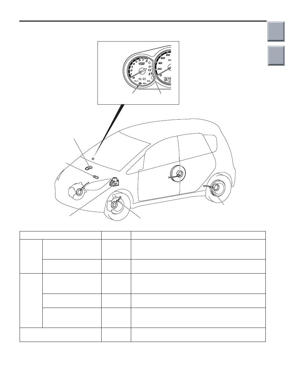
CONSTRUCTION DIAGRAM
AC400129AB
1
2
3, 7
1
4
5
6
Name of part
Number
Outline of function
Sensor
Wheel speed sensor
1
Sends alternating current signals at frequencies which are
proportional to the rotation speeds of each wheel to the
ABS-ECU.
Stop lamp switch
2
Sends a signal to the ABS-ECU to indicate whether the
brake pedal is depressed or and pump motor.
Actuator Hydraulic unit
3
Drives the solenoid valves and pump motor according to
signals from the ABS-ECU in order to control the brake
hydraulic pressure for each wheel.
ABS warning lamp
4
Illuminates in response to signals from the ABS-ECU
when a problem develops in the system.
Brake warning lamp
5
Illuminates in response to signals from the ABS-ECU
when a problem develops in the EBD system or the brake
fluid level is low.
Diagnosis connector
6
Outputs the diagnosis codes and allows communication
with the M.U.T.-III.
Main
Index
Group
TOC
Нет комментариевНе стесняйтесь поделиться с нами вашим ценным мнением.
Текст