Mitsubishi Colt Ralliart. Manual — part 721
TROUBLESHOOTING
MULTIPORT FUEL INJECTION (MPI) <4G1>
13B-209
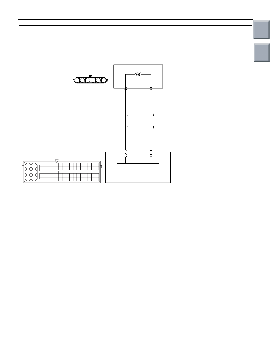
Code No. P2101: Throttle Valve Control Servo Magneto Malfunction
OPERATION
• Controls the current that is applied from the
engine-ECU (terminals No. 7, No. 22) to the elec-
tronic-controlled throttle valve (terminals No. 5,
No. 6).
FUNCTION
• Engine-ECU check whether the throttle valve
control servo magneto failed.
TROUBLE JUDGMENT
Check Conditions
• Ignition switch is in "ON" position.
• Battery voltage is more than 8.3 V.
Judgement Criterion
• Driving current of throttle valve control servo is
abnormal.
Or
• Temperature in driving circuit of throttle valve
control servo is abnormal.
PROBABLE CAUSE
• Failed throttle valve control servo.
• Open/short circuit in throttle valve control servo
circuit or lose connector contact.
• Failed engine-ECU
AK402696
6
1 2 3 4 5
19
21
20
18
17
16
15
14
1213
11
8 9
L
10
37
52 53 54 555657585960616263646566
38 39 404142434445464748495051
22 23 24 252627282930313233343536
7
5
3
1
6
4
2
AE
7
6
BR
G-W
Engine-ECU
Motor drive circuit
22
5
A-107
Throttle Valve Control Servo Circuit
A-114
Wire colour code
B: Black LG: Light green G: Green L: Blue W: White Y: Yellow SB: Sky blue BR: Brown O: Orange GR: Gray
R: Red P: Pink V: Violet
P: Purple
Electronic-controlled
throttle valve
Main
Index
Group
TOC

TROUBLESHOOTING
MULTIPORT FUEL INJECTION (MPI) <4G1>
13B-210
DIAGNOSIS PROCEDURE
STEP 1. Connector check: A-107
electronic-controlled throttle valve connector
Q: Is the check result normal?
YES :
Go to Step 2 .
NO :
Repair or replace.
STEP 2. Perform resistance measurement at
A-107 electronic-controlled throttle valve
connector.
• Disconnect connector, and measure at elec-
tronic-controlled throttle valve side.
• Resistance between terminal No. 5 and No. 6.
OK: 0.3
− 100 kΩ (at 20°C)
Q: Is the check result normal?
YES :
Go to Step 3 .
NO :
Replace throttle body assembly.
STEP 3. Connector check: A-114 engine-ECU
connector
Q: Is the check result normal?
YES :
Go to Step 4 .
NO :
Repair or replace.
AK402086
1
6 5 4 3 2
A-107(B)
AC
Connector: A-107
Harness side
connector
AK402086
1
6 5 4 3 2
A-107(B)
AC
Connector: A-107
Harness side
connector
AK402745
6
4
2
5
3
1
9
7
8
10
11
12
13
14
15
16
17
18
19
20
21
22
23
24
25
26
27
28
29
30
31
32
33
34
35
36
37
38
39
40
41
42
43
44
45
46
47
48
49
50
51
52
53
54
55
56
57
58
59
60
61
62
63
64
65
66
L
AF
A-114
Connector:
A-114
Harness side connector
Engine-ECU
Battery
Main
Index
Group
TOC

TROUBLESHOOTING
MULTIPORT FUEL INJECTION (MPI) <4G1>
13B-211
STEP 4. Check harness between A-107 (terminal
No. 6) electronic-controlled throttle valve
connector and A-114 (terminal No. 7) engine-ECU
connector.
• Check output line for short circuit and damage.
Q: Is the check result normal?
YES :
Go to Step 5 .
NO :
Repair.
STEP 5. Check harness between A-107 (terminal
No. 5) electronic-controlled throttle valve
connector and A-114 (terminal No. 22)
engine-ECU connector.
• Check output line for short circuit and damage.
Q: Is the check result normal?
YES :
Go to Step 6 .
NO :
Repair.
STEP 6. Check the trouble symptoms.
Q: Is the check result normal?
YES :
Replace engine-ECU.
NO :
Intermittent malfunction (Refer to GROUP
00
− How to Use
Troubleshooting/Inspection Service Points
−
How to Cope with Intermittent Malfunctions
).
AK402086
1
6 5 4 3 2
A-107(B)
AC
Connector: A-107
Harness side
connector
AK402745
6
4
2
5
3
1
9
7
8
10
11
12
13
14
15
16
17
18
19
20
21
22
23
24
25
26
27
28
29
30
31
32
33
34
35
36
37
38
39
40
41
42
43
44
45
46
47
48
49
50
51
52
53
54
55
56
57
58
59
60
61
62
63
64
65
66
L
AF
A-114
Connector:
A-114
Harness side connector
Engine-ECU
Battery
Main
Index
Group
TOC
TROUBLESHOOTING
MULTIPORT FUEL INJECTION (MPI) <4G1>
13B-212
Code No. P2108: Throttle Valve Control Servo Processor Malfunction
FUNCTION
• The engine-ECU checks the throttle valve control
servo processor for abnormal conditions.
TROUBLE JUDGMENT
Check Conditions
• Ignition switch is in "ON" position.
• Throttle position sensor (main) output voltage is
more than 0.2 V and is less than 4.8 V.
Judgement Criterion
• Throttle position sensor (main) input interface is
abnormal.
PROBABLE CAUSE
• Failed engine-ECU
DIAGNOSIS PROCEDURE
STEP 1. M.U.T.-III diagnosis code.
Q: Is any other diagnosis code than P2108 output?
YES :
Inspection chart for diagnosis code (Refer
to
NO :
Replace engine-ECU.
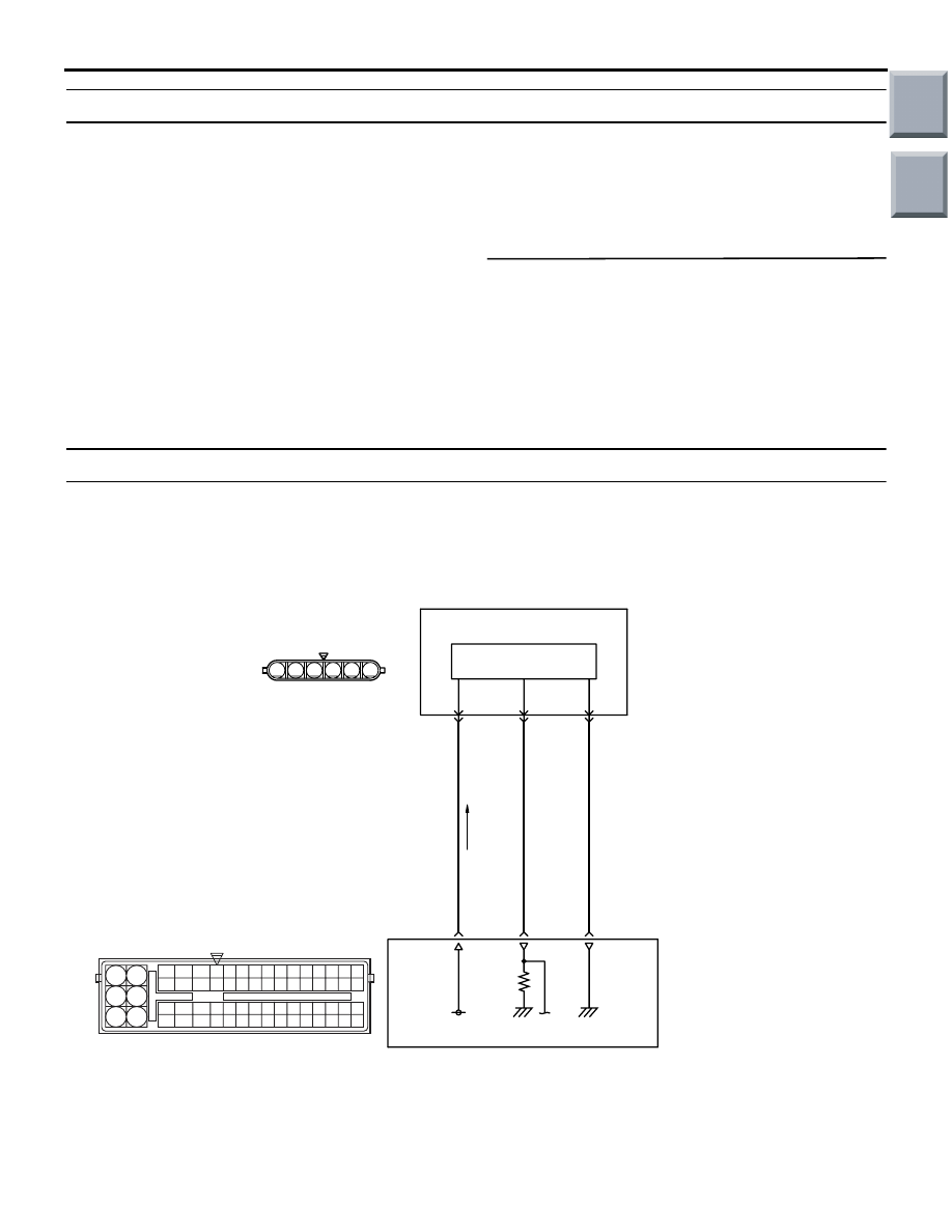
Code No. P2122: Accelerator Pedal Position Sensor (Main) Circuit Low Input
AK402685
R
92 93 94 95969798
77 78 79 808182838485868788899091
99
100
107 108 109 110 111112113114115116117118119120121
122 123 124 125126127128129130131132133134135136
101102103104105106
71 72
73 74
75 76
6
1 2 3 4 5
5 V
85
1
Accelerator
pedal
position
sensor
(main)
Hall IC
Y-G
GR
BR-W
83
84
3
2
Accelerator Pedal Position Sensor (main) Circuit
A-08
B-26
Wire colour code
B: Black LG: Light green G: Green L: Blue W: White Y: Yellow SB: Sky blue BR: Brown O: Orange GR: Gray
R: Red P: Pink V: Violet P: Purple
AD
Engine-ECU
Main
Index
Group
TOC
Нет комментариевНе стесняйтесь поделиться с нами вашим ценным мнением.
Текст