Mitsubishi Colt Ralliart. Manual — part 475
COMBINATION METER
CHASSIS ELECTRICAL
54A-45
DIAGNOSIS PROCEDURE
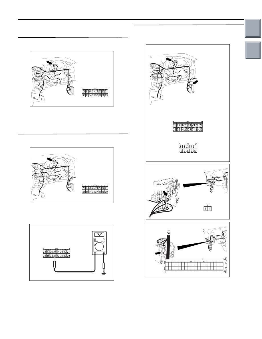
STEP 1. Connector check: Combination meter
connector B-14
AC313822AR
Connector: B-14
Harness side
B-14(B)
Q: Is the check result normal?
YES :
Go to Step 2.
NO :
Repair the defective connector.
STEP 2. Voltage measurement at combination
meter connector B-14.
AC313822AR
Connector: B-14
Harness side
B-14(B)
Disconnect the connector, and measure at the wiring
harness side.
• Ignition switch: LOCK (OFF) position
•
AC208309HW
Connector B-14
(Harness side)
Voltage between combination meter connector B-14
terminal No.33 and body earth
OK: System voltage
Q: Is the check result normal?
YES :
Go to Step 4.
NO :
Go to Step 3.
STEP 3. Check the harness wire between the
battery (fusible link No.1) and combination meter
connector B-14 terminal No.33.
AC313823
Connectors: B-14, B-22
AO
Harness side
B-14(B)
B-14
B-22
B-22
AC313824AN
Connector: B-108
Harness side
B-108(B)
AC313826AL
Connector: B-131
Harness side
16
34
21
19
1
20
2
28
4
22
3
23
5
9
27 26
8
10
13
31
12
30 29
11
15
33 32
14
35
17
36
18
7
25
6
24
NOTE: Prior to the wiring harness inspection, check
joint connector B-22 and junction block connectors
B-108 and B-131, and repair if necessary.
Q: Is the wiring harness between the battery (fusible
link No.1) and combination meter connector B-14
terminal No.33 in good condition?
YES :
Retest the system.
NO :
Repair the wiring harness.
Main
Index
Group
TOC

COMBINATION METER
CHASSIS ELECTRICAL
54A-46
STEP 4. Voltage measurement at combination
meter connector B-14.
AC313822AR
Connector: B-14
Harness side
B-14(B)
Disconnect the connector, and measure at the wiring
harness side.
• Ignition switch: ON
•
AC208309HX
Connector B-14
(Harness side)
Voltage between combination meter connector B-14
terminal No.31 and body earth
OK: System voltage
Q: Is the check result normal?
YES :
Go to Step 6.
NO :
Go to Step 5.
STEP 5. Check the harness wire between the
ignition switch (IG1) and combination meter
connector B-14 terminal No.31.
AC313823
Connectors: B-14, B-22
AO
Harness side
B-14(B)
B-14
B-22
B-22
AC313827AJ
Connectors: B-129, B-131
Harness side
16
34
21
19
1
20
2
28
4
22
3
23
5
9
27 26
8
10
13
31
12
30 29
11
15
33 32
14
35
17
36
18
7
25
6
24
B-129
B-131
B-129
B-131
NOTE: Prior to the wiring harness inspection, check
joint connector B-22 and junction block connectors
B-129 and B-131, and repair if necessary.
Main
Index
Group
TOC

COMBINATION METER
CHASSIS ELECTRICAL
54A-47
Q: Is the wiring harness between the ignition switch
(IG1) and combination meter connector B-14
terminal No.31 in good condition?
YES :
Retest the system.
NO :
Repair the wiring harness.
STEP 6. Voltage measurement at combination
meter connector B-14.
AC313822AR
Connector: B-14
Harness side
B-14(B)
Disconnect the connector, and measure at the wiring
harness side.
• Ignition switch: ON
•
AC208309HY
Connector B-14
(Harness side)
Voltage between combination meter connector B-14
terminal No.32 and body earth
OK: System voltage
Q: Is the check result normal?
YES :
Go to Step 8.
NO :
Go to Step 7.
STEP 7. Check the harness wire between the
ignition switch (IG2) and combination meter
connector B-14 terminal No.32.
AC313822AR
Connector: B-14
Harness side
B-14(B)
NOTE:
AC313826AK
Connector: B-130
Harness side
Prior to the wiring harness inspection, check junction
block connectors B-130, and repair if necessary.
Q: Is the wiring harness between the ignition switch
(IG2) and combination meter connector B-14
terminal No.32 in good condition?
YES :
Retest the system.
NO :
Repair the wiring harness.
Main
Index
Group
TOC

COMBINATION METER
CHASSIS ELECTRICAL
54A-48
STEP 8. Resistance measurement at combination
meter connector B-14.
•
AC313822AR
Connector: B-14
Harness side
B-14(B)
Disconnect the connector, and measure at the wiring
harness side.
•
AC208309HZ
Connector B-14
(Harness side)
Resistance between combination meter connector
B-14 terminal No.23 and body earth
OK: Continuity exists (2
Ω or less)
•
AC208309IA
Connector B-14
(Harness side)
Resistance between combination meter connector
B-14 terminal No.36 and body earth
OK: Continuity exists (2
Ω or less)
Q: Is the check result normal?
YES :
Go to Step 10.
NO :
Go to Step 9.
STEP 9. Check the harness between combination
meter connector B-14 terminal No.23, No.36 and
body earth.
AC313823
Connectors: B-14, B-25
AP
Harness side
B-14(B)
B-14
B-25
B-25
NOTE: Prior to the wiring harness inspection, check
joint connector B-25, and repair if necessary.
Q: Is the wiring harness between the combination
meter connector B-14 terminal No.23, No.36 and
body earth in good condition?
YES :
Retest the system.
NO :
Repair the wiring harness.
STEP 10. Retest the system.
Q: Is the check result normal?
YES :
The trouble can be an intermittent
malfunction (Refer to GROUP 00, How to
Cope with Intermittent Malfunction
NO :
Replace the combination meter.
Main
Index
Group
TOC
Нет комментариевНе стесняйтесь поделиться с нами вашим ценным мнением.
Текст