Mitsubishi Colt Ralliart. Manual — part 651
CAMSHAFT AND VALVE STEM SEAL
ENGINE MECHANICAL <4G1>
11C-24
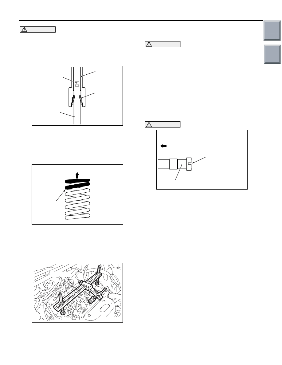
CAUTION
• Do not re-use the valve stem seal.
•
AC107414
AF
MB991671
Valve
Valve stem
seal
Valve guide
Special tool valve stem seal installer
(MB991671) must be used to install the valve
stem seal. Improper installation could result
in oil leaking past the valve guide.
3. Use special tool valve stem seal installer
(MB991671) to fill a new valve stem seal in the
valve guide using the valve stem area as a guide.
>>B<< VALVE SPRING INSTALLATION
AC201453
AB
Rocker arm side
Identification
colour
Install the valve spring with its identification colour
painted end facing the locker arm.
>>C<< VALVE SPRING RETAINER LOCK
INSTALLATION
AC402635
MD998772
AB
Use special tool valve spring compressor
(MD998772) to compress the valve spring in the
same manner as removal.
>>D<< ROCKER ARM LASH ADJUSTER
INSTALLATION
CAUTION
If the rocker arm lash adjuster is reused, always
clean and check it before installation.(Refer to
GROUP 11D, Rocker Arms and Camshaft
).
>>E<< EXHAUST CAMSHAFT/INLET
CAMSHAFT INSTALLATION
1. Remove sealant remained on the engine cylinder
head.
2. Apply engine oil to the cam and the journal of the
camshaft.
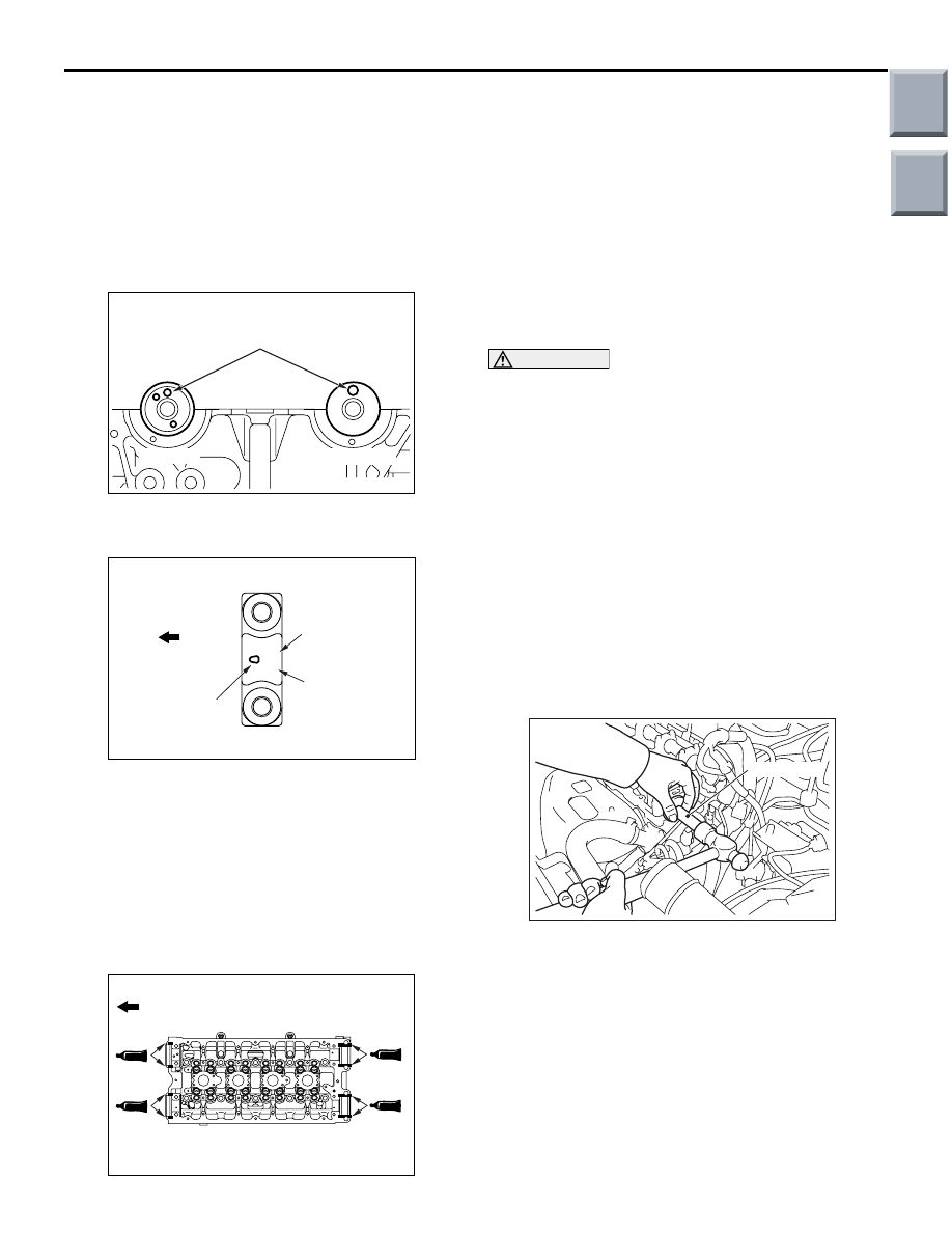
AC205419
AB
Engine front
Slit
Inlet camshaft
CAUTION
Do not install wrong camshaft at the side of inlet
or exhaust. The inlet camshaft has a slit at the
rear surface.
3. Install the camshaft to the engine cylinder head.
Main
Index
Group
TOC
CAMSHAFT AND VALVE STEM SEAL
ENGINE MECHANICAL <4G1>
11C-25
>>F<< CAMSHAFT BEARING CAP, NO.
4/CAMSHAFT BEARING CAP, NO.
3/CAMSHAFT BEARING CAP, NO.
5/CAMSHAFT BEARING CAP, NO.
2/CAMSHAFT BEARING CAP, REAR
LEFT/CAMSHAFT BEARING CAP,
FRONT/CAMSHAFT BEARING CAP,
REAR RIGHT INSTALLATION
AC205421
AB
Dowel pin
Exhaust side
Inlet side
1. Set the dowel pin of the camshaft to the position
as shown in the illustration.
AC205417
E 4
AB
Bearing cap No.
Identification of
inlet side and
exhaust side
Engine front
Front mark
2. Camshaft bearing caps (No.2 to 5) are identical.
To avoid confusion (bearing cap No. and
inlet/exhaust side), confirm each identification
mark and face the front mark towards the
direction shown before installing them.
Identification mark (engraved on the front
and bearing caps No.2
− 5)
I: Inlet side
E: Exhaust side
AC207568
AB
Engine front
3. Apply sealant to the positions (8 areas) of the
upper side of the cylinder head as shown in the
illustration.
Specified sealant: MITSUBISHI GENUINE
PART MD970389 or equivalent
NOTE: Install the camshaft bearing caps, rear and
camshaft bearing caps, front within 15 minutes
after applying sealant.
4. Check the identification marks on the camshaft
bearing cap, front so that inlet side and exhaust
side cannot be mistaken in the same way as that
of bearing caps No.2
− 5.
CAUTION
Then wait at least one hour. Never start the
engine or let engine oil or coolant touch the
adhesion surface during that time.
5. Tighten the bearing cap mounting bolts increasing
the pressure in 2 to 3 times and finally tighten to
the specified torque.
Tightening torque:
25
± 1 N⋅m <Camshaft bearing cap, front and
rear>
11
± 1 N⋅m <Camshaft bearing cap No.2 - 5>
6. Ensure that the rocker arms are installed properly.
NOTE: Remove an excess of sealant completely.
>>G<< CYLINDER HEAD CAMSHAFT
END SEAL INSTALLATION
AC402626
MD998762
AB
Use special tool circular packing installer
(MD998762) to press-fit the cylinder head camshaft
end seal as shown.
Main
Index
Group
TOC
CAMSHAFT AND VALVE STEM SEAL
ENGINE MECHANICAL <4G1>
11C-26
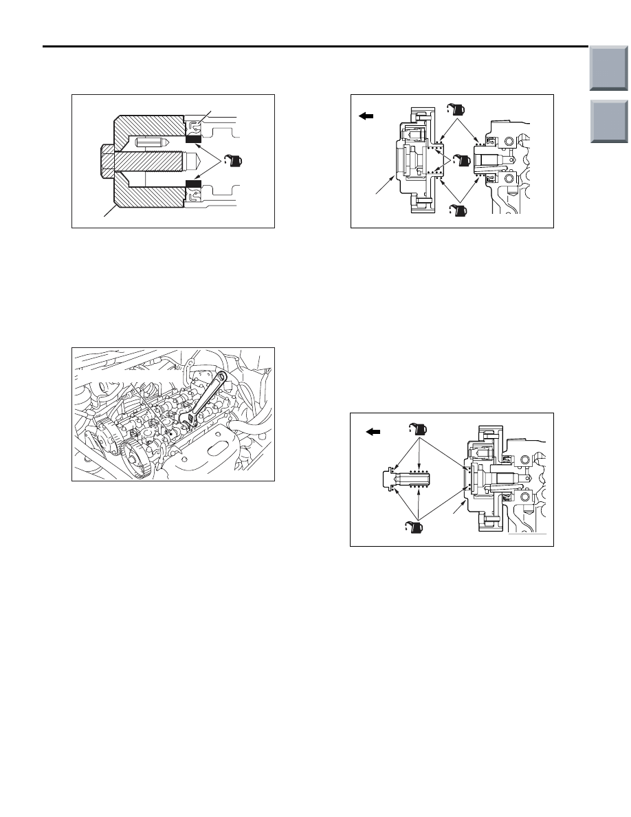
>>H<< CAMSHAFT OIL SEAL
INSTALLATION
AC102323AC
MD998713
Camshaft oil seal
(Engine oil)
1. Apply engine oil to the entire inner diameter of the
oil seal lip.
2. Use special tool camshaft oil seal installer
(MD998713) to press-fit the oil seal as shown.
>>I<< CAMSHAFT SPROCKET (EXHAUST
SIDE) INSTALLATION
AC402637AB
Camshaft (Exhaust side)
1. Hold the hexagon part of the camshaft with a
wrench.
2. Install the camshaft sprocket and tighten the
camshaft sprocket mounting bolt to the specified
torque.
Tightening torque: 88
± 10 N⋅m
>>J<< CAMSHAFT SPROCKET (INLET
SIDE) INSTALLATION
AC207579
Engine front
AB
(Engine oil)
Camshaft
sprocket
(Inlet side)
1. Apply engine oil to the tip of the camshaft and the
camshaft installation side of the camshaft
sprocket.
2. Align the dowel pin hole of the camshaft sprocket
with the dowel pin of the camshaft, and install the
camshaft sprocket to the camshaft.
3. While holding the hexagonal area of the camshaft
with a wrench, check that the camshaft sprocket
does not turn.
NOTE: This is necessary, because you cannot
confirm that the camshaft dowel pin is inserted
into the pin hole.
AC207580
AB
Engine front
(Engine oil)
Camshaft
sprocket
(Inlet side)
4. Apply the engine oil to the threads and the face of
the camshaft sprocket mounting bolt. Then fix the
camshaft with a wrench in the same way as
removal and tighten the camshaft sprocket
mounting bolt to the specified torque.
Tightening torque: 55
± 5 N⋅m
Main
Index
Group
TOC

CAMSHAFT AND VALVE STEM SEAL
ENGINE MECHANICAL <4G1>
11C-27
>>K<< CAMSHAFT POSITION SENSING
CYLINDER INSTALLATION
1. Set the inlet camshaft to the No.1 cylinder at
compression TDC.
NOTE: Use the force of the exhaust valve spring
to rotate anti-clockwise.
AC205420
AB
Camshaft position
sensing cylinder
2. Install the camshaft position sensing cylinder as
shown, and tighten the camshaft position sensing
cylinder mounting bolt to the specified torque.
Tightening torque: 22
± 4 N⋅m
>>L<< CAMSHAFT POSITION SENSOR
SUPPORT INSTALLATION
1. Remove sealant from the camshaft position
sensor support and cylinder head surfaces.
AC205422
f3 mm
AB
2. Apply the sealant to the camshaft position sensor
support flange in a continuous bead as shown in
the illustration.
Specified sealant: MITSUBISHI GENUINE
PART MD970389 or equivalent
NOTE: Install the camshaft position sensor sup-
port within 15 minutes after applying sealant.
3. Install the camshaft position sensor support to the
cylinder head.
CAUTION
Then wait at least one hour. Never start the
engine or let engine oil or coolant touch the
adhesion surface during that time.
4. Tighten the camshaft position sensor support
mounting bolts to the specified torque.
Tightening torque: 14
± 1 N⋅m
>>M<< ROCKER COVER ASSEMBLY
INSTALLATION
AC500202
1, 11
2, 12
4, 14
3, 13
8
9
10
7
6
5
Engine front
AB
1. Tighten the each bolt to 5.0
± 1.0 N⋅m in the order
(1
−14) shown.
2. After tightening of step 1, tighten the each bolt to
7.0
± 1.0 N⋅m in the order (1−10) shown.
>>N<< OIL CONTROL VALVE
INSTALLATION
1. Apply a small amount of engine oil to the O-ring
and then install it to the oil control valve.
2. Assemble the oil control valve to the cylinder
head.
3. Tighten the oil control valve mounting bolt to the
specified torque.
Tightening torque: 11
± 1 N⋅m
Main
Index
Group
TOC
Нет комментариевНе стесняйтесь поделиться с нами вашим ценным мнением.
Текст